Floor Analysis
The floor analysis feature allows you to create a floor flatness and floor levelness report based on scan data. It also allows you to create contour lines and a grid of points that can be used to aim the instrument at the high and low points.
Floor Flatness and Floor Levelness
To create a floor flatness and floor levelness report:
- Tap the Scan icon
 in the menu bar and then tap Floor Analysis towards the bottom of the menu.
 - Make sure the Floor Flatness/Floor Levelness icon
 is selected in the bottom left-hand corner.
 - Tap the Floor Selection
 tool located above the information ribbon to open the menu.
 - Tap the + icon to add a new floor.
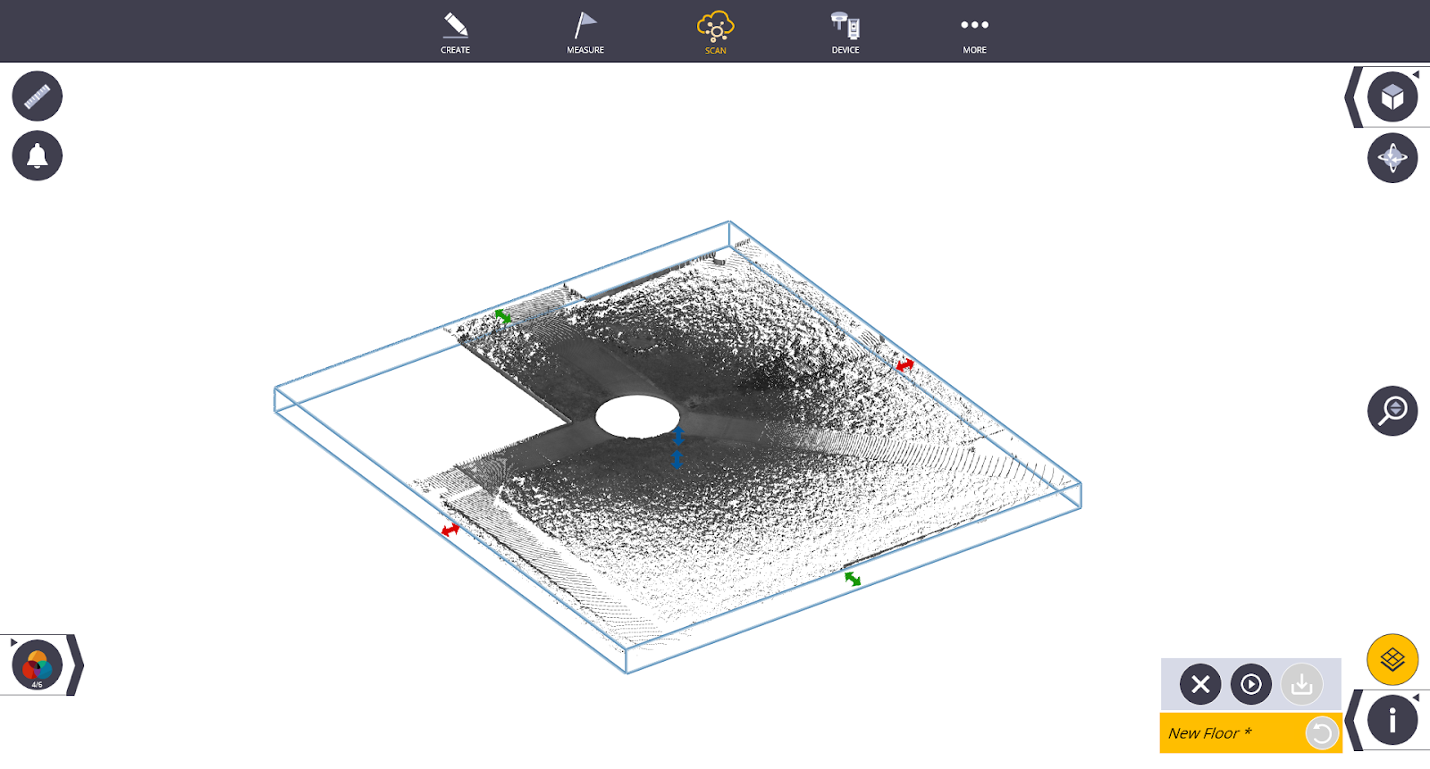
- Use the red, green and blue arrows to move the limit box to show only the floor of the area you would like to analyze, being sure to adjust the Z-axis as well.
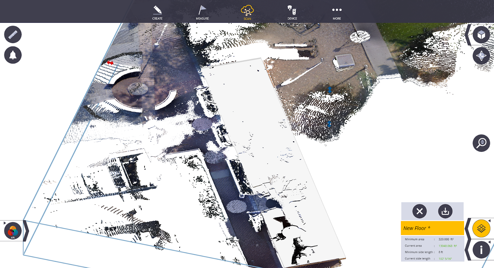
- Once you have selected the region you want to analyze, tap the Confirm
 icon. The floor is extracted with the selected points.
 - Tap the Save
 icon to save the extracted floor.
 - You can select the Edit icon at any point to change the name or assigned layer of this extracted floor.
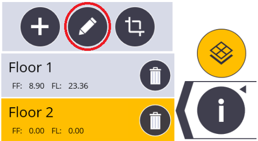
- To readjust the selected floor from the current extracted points, tap the Crop
 icon next to the edit icon. This will delete the current saved floor.
 - Once you are satisfied with the extracted floor, close the floor selection tool by tapping the floor selection icon.
- The software prompts you to add sample lines to the floor. Based on the minimum number of reading requirements that is generated based on the size and density of the point cloud, you may have to create several lines to meet this requirement. Select the + icon to create a line. The minimum line length is 11ft.
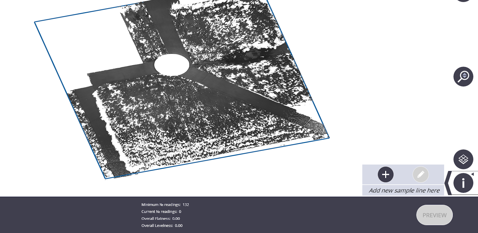
- To create a line, tap one point on the floor and then drag your finger across the floor a short distance away from the first point to determine the length of line you would like to use. You can adjust this line by tapping and dragging the endpoints or by tapping and dragging the complete line.
- When you are satisfied with the length and location of the line, tap Accept.
- Repeat this process until you have met the minimum number of reading requirements. You can alternate the direction of the lines as well as overlap them. When you have met the minimum number of readings, the Preview button appears.
-
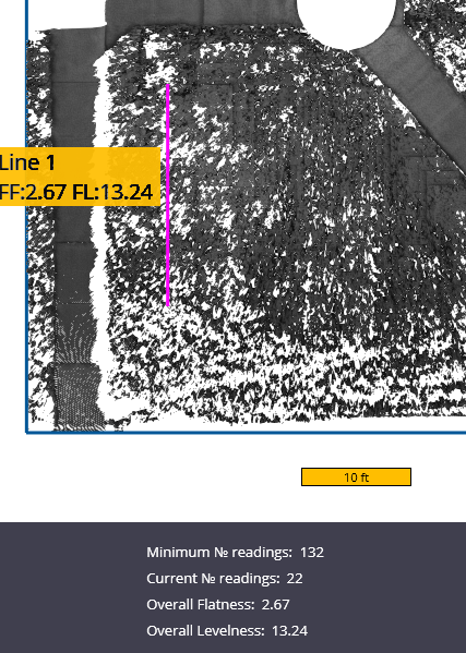
In the preview menu, you can edit the minimum local value and specified overall value for both the floor flatness and floor levelness. Once complete, tap the preview button to view the report. To go back to the map, tap the Map icon.
-
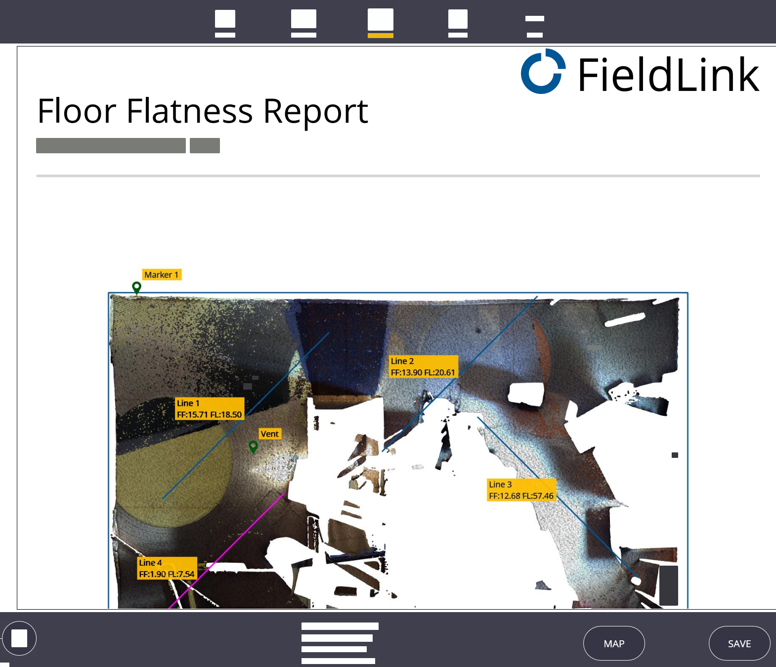
The Floor Flatness Report is automatically generated in a browser link and presented to you once it finishes processing.
-
Right-click the report to save the .html report or to print the report as a PDF to a folder of your choosing.
Contour and Point Creation
To create contour lines and points that allow the instrument to aim to:
- Tap the Scan icon in the menu bar and select the Floor Analysis option near the bottom of the menu.
- Make sure the Floor Contours icon
 is selected in the bottom left-hand corner.
 - Select the Floor Selection tool located above the information ribbon to open the menu.
- Tap the + icon to add a new floor. If you have already extracted a floor, select which one you would like to analyze and skip to step 9.
- Use the red, green and blue arrows to move the limit box to show only the floor of the area you would like to analyze.
- Once you have selected the region you want to analyze, tap the Confirm icon . The floor is extracted with the selected points
- Once the extraction is successful, tap the Save icon to save the extracted floor. You can select the Edit icon at any point to change the name or assigned layer of the extracted floor.
- To readjust the selected floor from the current extracted points, select the Crop icon next to the edit icon. This will delete the current saved floor.
- Once you are satisfied with the extracted floor, exit the floor selection tool by tapping on the Floor Selection icon again.
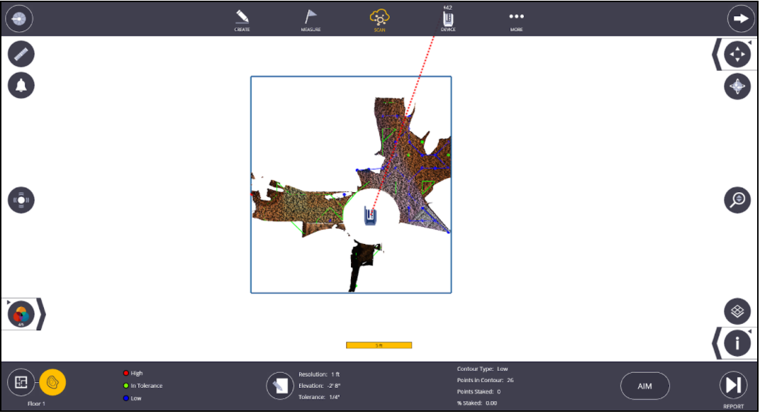
- The contour lines along with the high, in tolerance, and low points are automatically generated based on the tolerance specifications you set in the edit menu. To change the resolution (distance between points), elevation and tolerance, tap the Edit icon in the bottom center of the screen.
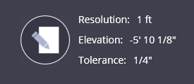
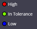
- Once your tolerance settings are adjusted, tap the Edit icon again to reprocess the grid.
- To change the floor elevation outside of the edit menu, use the Touch Scan Point
 icon and select the individual scan point you would like to change the elevation to.
- Once you are satisfied with the contours, select the Finalize button
 on the right hand side of the screen.
 - The individual points are generated and shown on screen. Tap the Edit icon on the bottom of the screen to edit the name, description and layer to save the points under. Once complete, select the edit icon again to close this screen.
TIP – If you plan to export the generated points as a CSV file, provide a unique description or layer to easily separate these points from other points created in the project. The points extracted from the floor analysis are automatically added to a default layer named “Floor X”
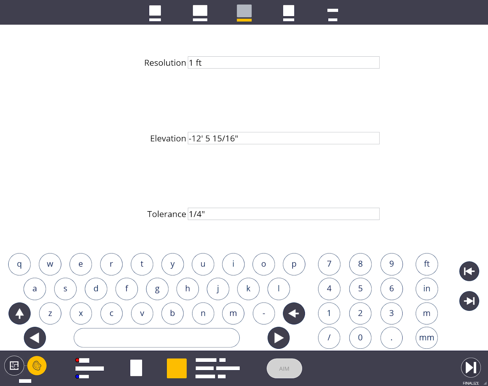
- To view the Floor Report, tap the Report button
 on the bottom of the screen.
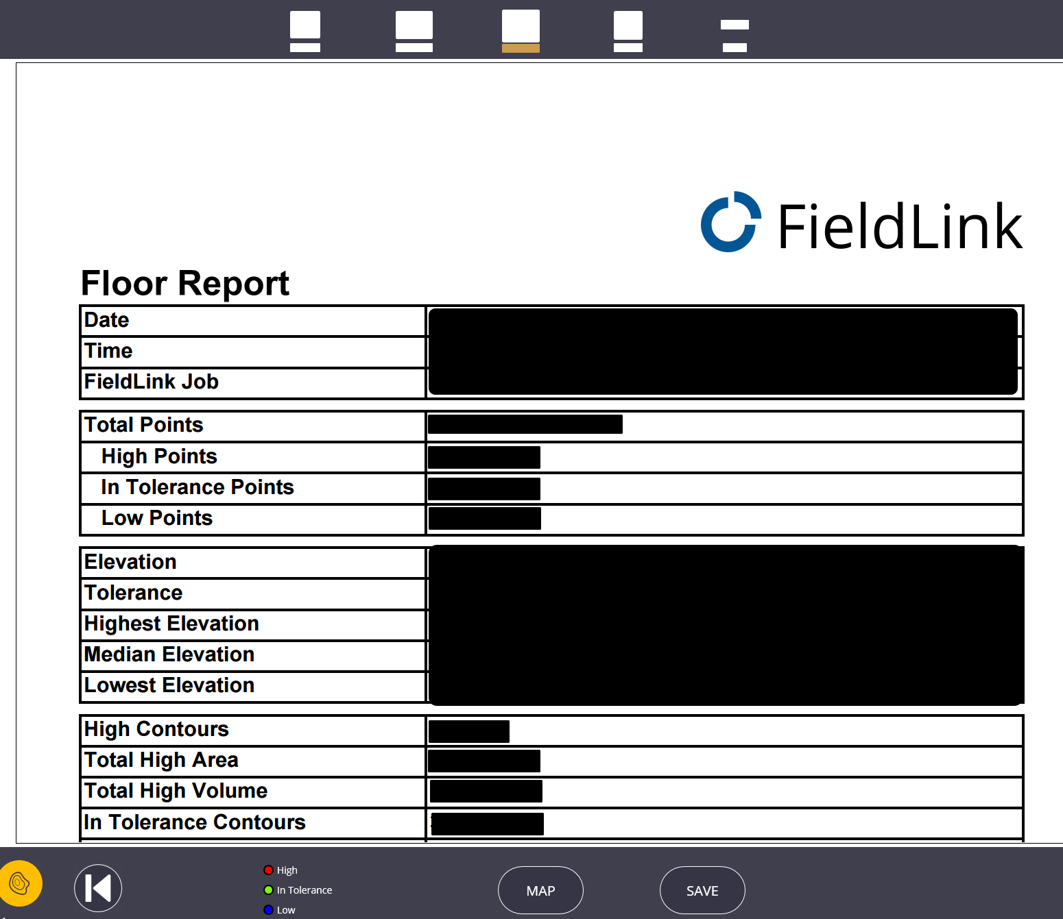
- Once in the report preview screen, you can either return to the map view or save the report to your desired location.
- To view the generated points report as a CSV file, navigate to More > Projects > Export and filter out the floor points you would like to export. Select CSV as the file type and the press Export.
- The default save location for the reports is User > Documents > FieldLink > Reports > Floor Reports and the default location for CSV exports is User > Documents > FieldLink > Exports.
Contour and Point Layout
Once you have collected a scan of the area around you, generated the contour lines and have set-up the instrument on two points, you can now use the instrument to aim at the high and low points on the contour lines. To do this:
- Ensure the instrument is set up by tapping Device
 and then tapping Set Up.
 - Go to the Floor Inspection contour creating menu by tapping Scan > Floor Analysis > Contour Creation.
- Once the contour lines have been created and the instrument is leveled and set up, select the contour line to layout. The individual points that make up that line appear.
- Tap the point you would like to aim the laser pointer at.
- The Aim button should appear solid. Tap the Aim button.