Total Station Setup
This section covers setting up the total station before you start. Depending on your requirements, you can set up the total station using one of the following methods:
Set Up - No Data
When you are starting a job with no reference data or points you can create your own arbitrary reference for instrument setup. FieldLink offers two ways to do this, north facing setup and two points with elevation setup.
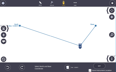
North Facing Setup 
- Point the device in the desired direction.
- Tap Set.
North Facing 2 Point Setup 
- Create a new job.
- Tap the Device
 icon and then tap Setup.
 - Measure two points.
- Use Input Form
 to enter Elevation.
 - Select North and Base coordinates.
- Use Rotation icons to orientate coordinates.
- Tap Set.
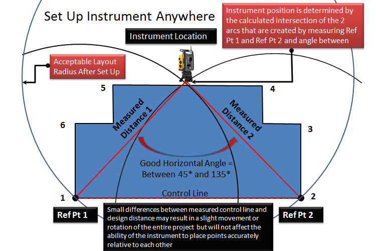
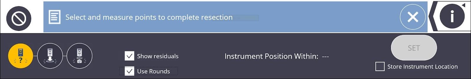
Set Up - Unknown Location (Resection)
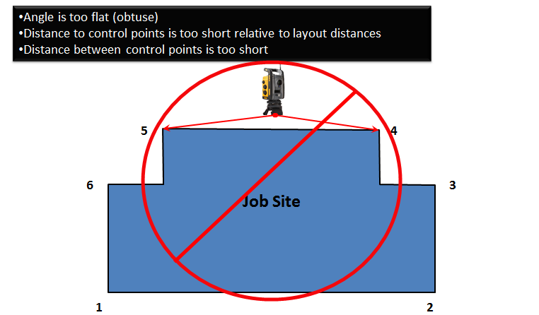
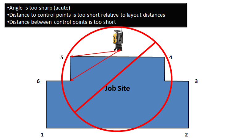
The RTS can be placed in a convenient location as long as there are at least two control points with a known location in the field of view. It is best practice to have the angle between the control points be within 45 and 135 degrees. The angle requirements help to ensure a more accurate calculation of the instrument position. If two control points are not between 45 and 135 degrees, or for a more refined set up, measure 3 or more control points and select the best measurements.
FieldLink uses a least square algorithm and computes the mean to determine station locations. The software computes the mean error for both horizontal and vertical calculations and display the horizontal error in the application. An unknown location (resection) requires a minimum of two measured locations preferably at 90 degrees to each other. Using more points improves the calculation. To get the best results, it is desirable that each point used is equally spaced from each other around the total station at ranges that are greater or equal to the furthest expected layout/collection point.
You can accept “unreliable” instrument setups if two control points within the 45 to 135 degree triangle are not available. You can tap Set even with the unreliable set up, but be cautious about laying out new points and be sure to check back to previously laid out points if possible. The best practice is to add a third or fourth control point to the instrument set up to ensure accuracy and proper angular measurements.
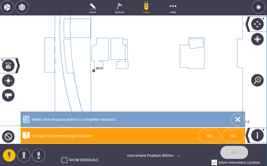
- Tap the Device icon and then tap the Set Up icon.
- Tap on the first control point to be measured so it is highlighted with a blue circle. Make sure the rod height and prism type are correct in the Prism Settings, and the RTS is locked onto the prism at the correct point location (or pointed at the control point target directly in laser mode).
- Tap the Shoot icon in the upper right corner.
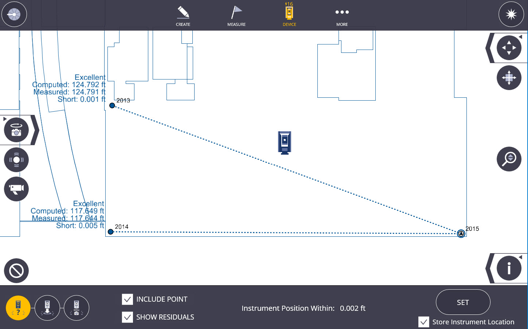
- Once the point has been measured, it is shown as a solid blue circle.
- You can now uncheck the Include box for each measured point if you do not want the point included in the Set Up calculations.
- Tap on the second control point to be measured so it is highlighted with a blue circle. Make sure the rod height and prism type are correct in the Prism Settings, and the RTS is locked onto the prism at the correct point location (or pointed at the control point target directly in laser mode).
- Tap the Shoot icon.
- If the two points are within the 45 to 135 degree triangle, the Instrument Position Within calculation shows a measurement.
- If the two points are under 45 degrees or outside 135 degrees apart, the software labels the set up as “unreliable”. You can tap the Set icon to accept this set up or measure another point to add it to the calculations.
- If necessary, tap on the third control point to be measured so it is highlighted with a blue circle.
- Tap the Shoot icon. Repeat this process for additional control points as needed.
- If you shoot more than 2 control points, you can tap on each measured point and uncheck the Include box in the lower message bar and see how it affects the calculated position next to Instrument Position Within dialogue box.
- You can reshoot each point at any time by tapping on the measured point and tapping the Shoot icon.
- Tap Set once you are satisfied with the results. Alternatively, tap the Clear icon to clear all measurements and start over.
Set Up - Unknown Location (Resection) - Angles Only
Angles Only Resection Setup is performed the exact same way as a traditional resection, except a traditional resection takes into account the angles and distances from the instrument position to the control points while an angles only setup ONLY takes into consideration the angles from the instrument to the control points. This setup type is useful when you need to use control points with permanent prisms that have been placed on a job site beforehand, and you may not know the type of prism or the prism constant to input for the prism type.
Set Up - Known Point
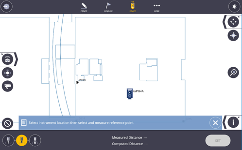
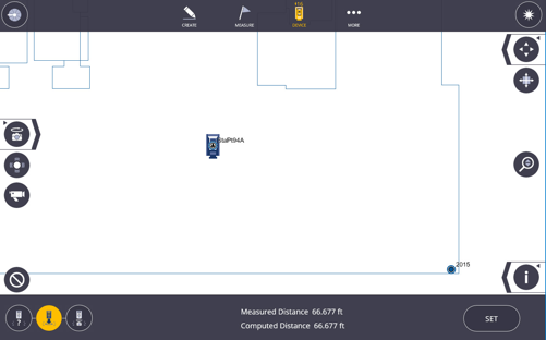
On the jobsite, it may be convenient to set up the RTS on a known point to conduct the layout. Another known reference point is required to complete the setup.
- Tap the Device icon and then tap Setup.
- Tap Known Location icon.
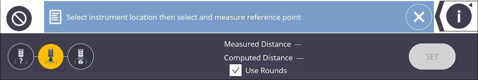
- Tap Instrument Location point on map then select & measure reference point.
- Tap Set.
Known Point Setup - Ri Laser Plummet
You can use the Ri laser as a plummet for station setup.
- Set up the Ri roughly above the point on which you would like the Ri to be located.
- Tap the Device icon and then tap Setup.
- Tap Known Location icon.
- Tap the Plummet icon.

- If the laser is +6” away from the desired point, gently move the tripod legs and instrument until the laser is within 6” of the point.
- Level the instrument by adjusting the tripod legs and tribrach adjustment screws.
Adjusting the level of the instrument, whether with the tripod legs or the tribrach adjustment screws, moves the laser on the ground. If after leveling the instrument the laser is beyond 6” from the point of interest, move the instrument again until the laser is within 6” and adjust the instrument level again.
- The laser will still not be above the point after leveling the instrument. To fine tune its position, slide the tribrach on the top plate of the tripod legs until the laser is above the desired point.
- If this instrument goes out of level with this last step, redo steps 6 and 7.
Set Up - Panorama
By using the panorama picture taken with the RTS device you have the option to use the panorama to select targets and have the instrument automatically measure the targets and assign them to execute a station setup. Here are the steps to complete a panorama setup:
- Tap the Device icon and then tap Setup.
- Tap the Panorama Setup icon
 .
. - If you have a panorama that you have just taken it is displayed on the screen, if you have a saved panorama from the existing station tap Open and select the panorama or tap Take New to capture a new panorama.
- You are prompted to select at least 2 targets in the panorama. Scroll around the panorama and select the targets.
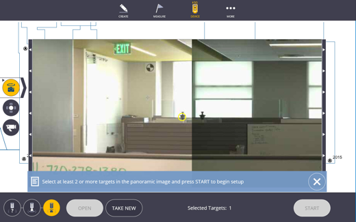
- Tap Start. The instrument automatically turns, locks onto and measures each target.
- A toast message will appear stating "Unable to resolve instrument position" and asking you to select a point on the map that the instrument is currently aiming at. Select a point on the map screen and tap Assign. The instrument will then point to the next target, repeat the process for each target.
- Select option to Store Instrument Location if desired.
- Tap Set.
Set Up - Use Rounds (Optional Module)
If you have purchased the optional Site Control Module, you can choose the Use Rounds option for both the Known and Unknown Location Set Up.
- Tap the Device icon and then tap Setup.
- Tap the Known or Unknown Setup icon.
- Check the Use Rounds box.
- You will then be prompted to set the Face Order (F1/F2, F2/F1, or F1 only), the number of rounds (shoot each point 1 - 10 times), and measure mode (high or fast precision).
- Press the Shoot icon to start the rounds collection process.

Set Up - Grid Lines
NOTE – For absolute best accuracy setup, Trimble recommends using a standard resection instead of grid line setup. Only use a grid line setup as a last resort.
- Tap the Device icon and then tap Setup.
- Tap the Grid Line Setup icon.
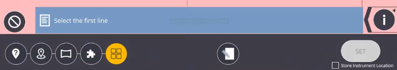
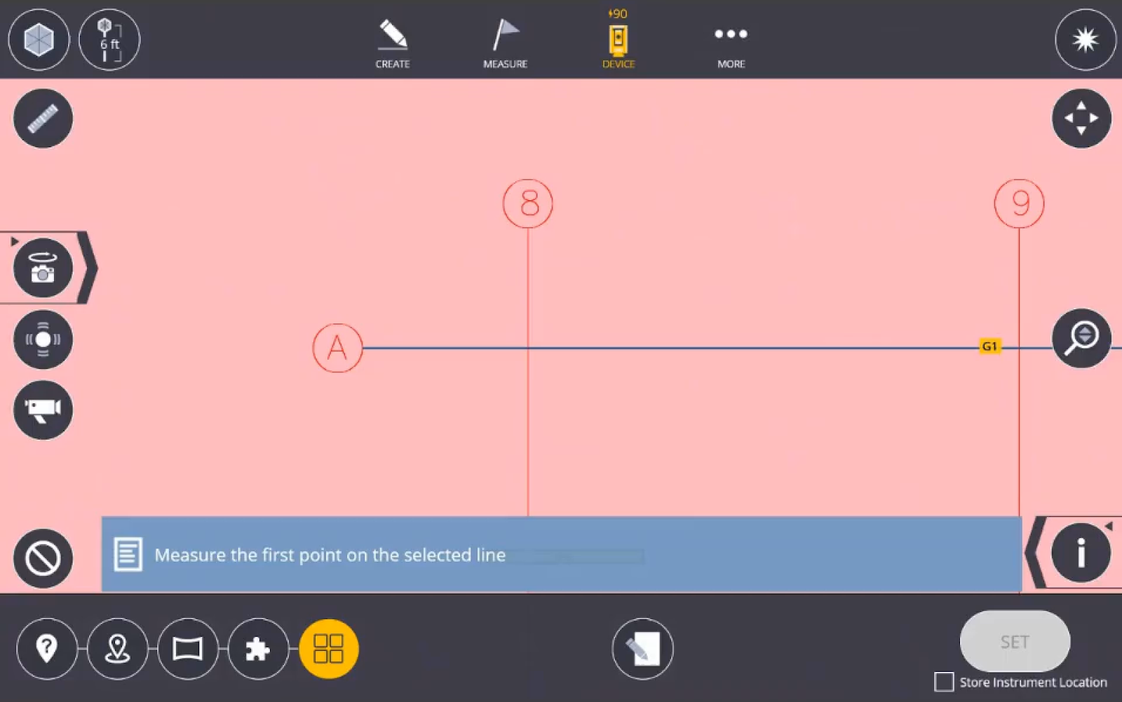
- Tap the first grid line.
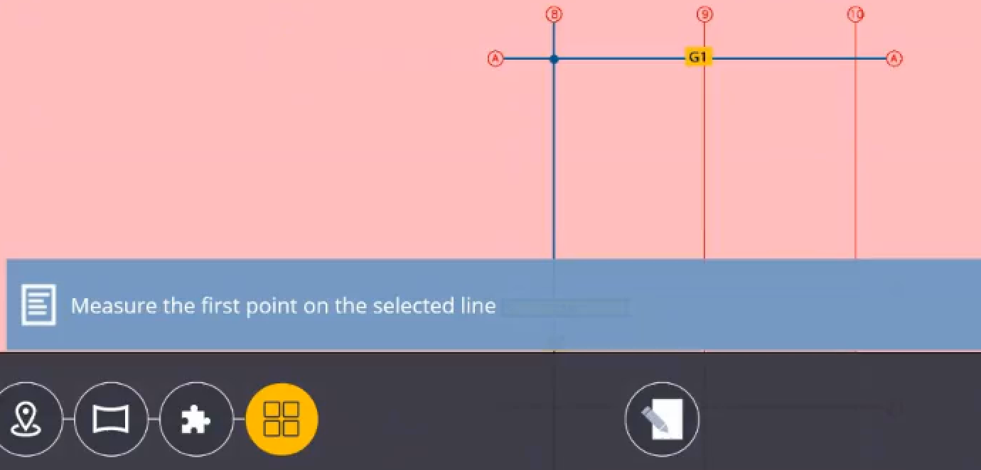
- Measure the first point on the selected grid line.
- Measure the second point along the same grid line.
- Tap the second grid line.
- Measure the first point along the grid line.
- Measure the second point along the grid line.
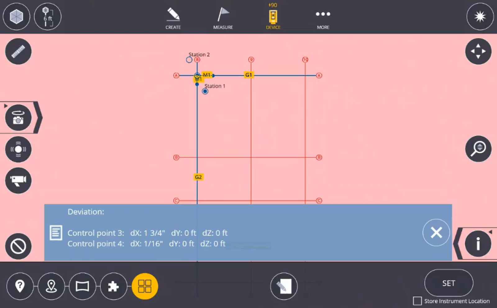
- Select the station to position the instrument.
- If the Deviation is acceptable and then tap Set.
- Once Set is selected, a message indicates that a reference elevation is recommended for the setup. Select the Reference Elevation button to aim the instrument to a feature, take a measurement and input the elevation of choice to use as reference for the rest of the setup.

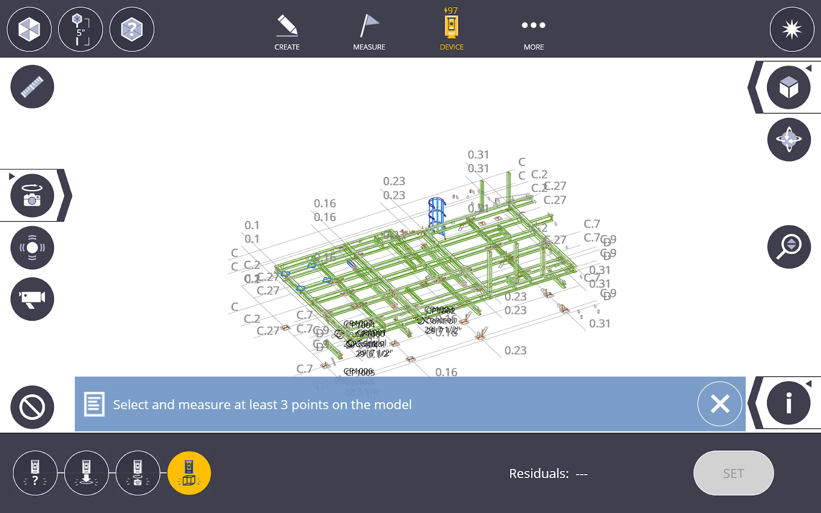
Component Based Set Up
This feature enablea you to set up on an unlevelled surface to help with fabrication items and ensure accuracy to the modeled item.
NOTE – When using a scanner Trimble recommends using only one scan.
With the Component Based Set Up, a rigid transformation of the model is performed, requiring at least three points. When there are more than three points, a least squares solution is obtained. The centroids of the map data and the measurement data is calculated. This allows the software to calculate optimal rotation and translation matrices that are used to find the setup location. Error is the square distance error between the points in the two datasets.
-
Tap the Device icon
and then tap Setup. -
Tap the Component Based Set Up icon.
-
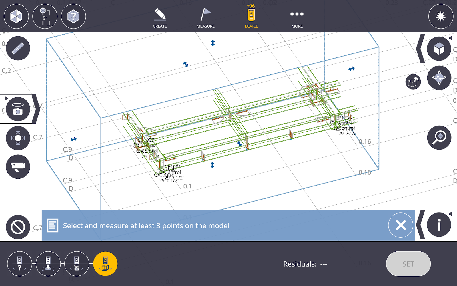
Select and measure at least 3 points on the component to set the new level for the component. Use the Layer and/or Section Box Tools to isolate a specific component to use for set up and layout.
NOTE – Points do not need to be created before using the tool. You have the ability to create necessary points on the model for use in their component based setup.
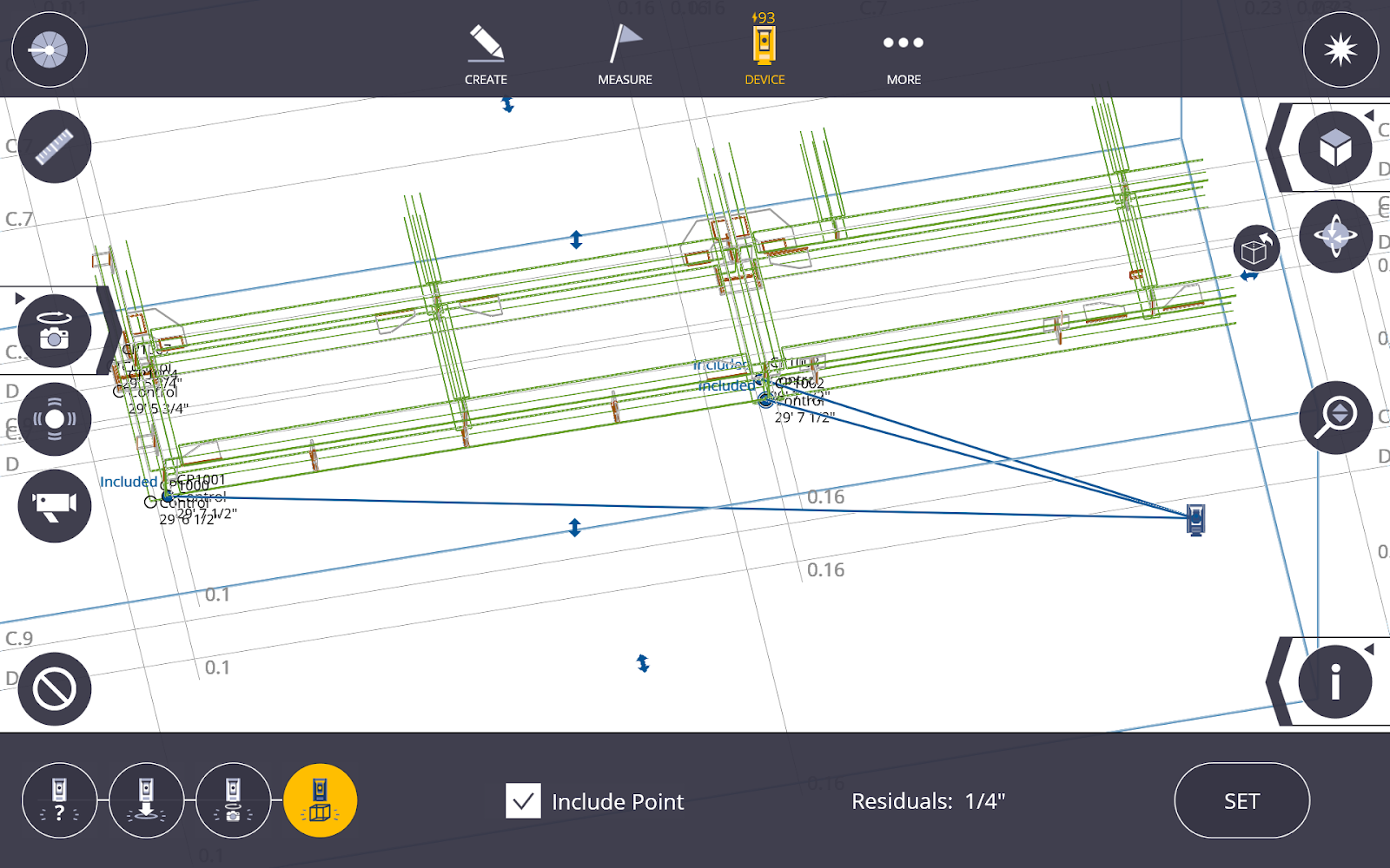
-
Once you measure at least 3 points, the position of the instrument and a residual setup error is shown. Tap Set to complete the setup and start laying out additional component connection points.
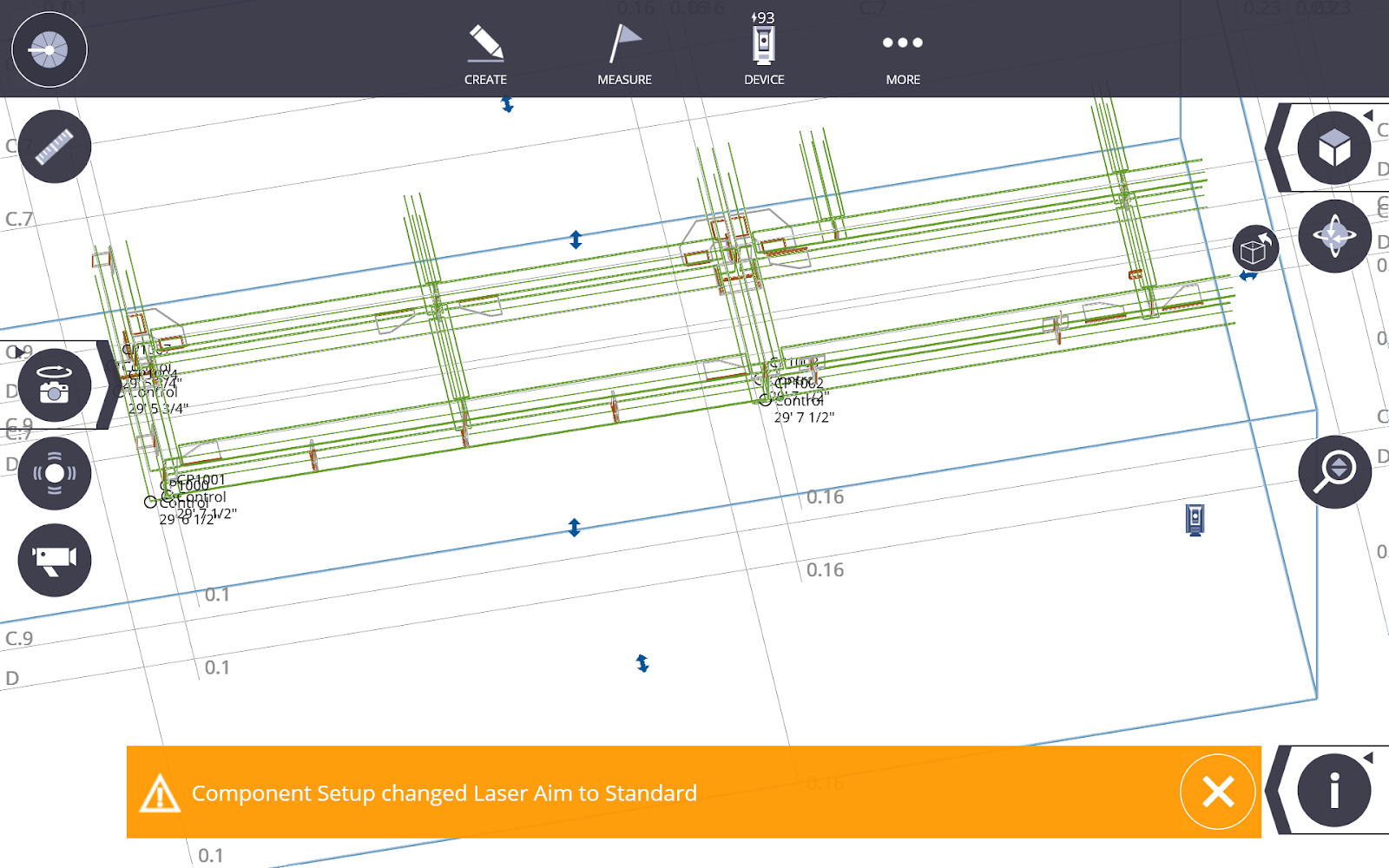
- To process the new component level, the software changes the laser to standard aim instead of visual layout.
Retain Station Setup
If you have performed a station setup (total Station, GNSS or scanner setup), you can retain that setup and the control points used for the setup when changing jobs within one project. This means you can navigate efficiently between layout jobs in one project without having to re-setup the instrument.