Parts of the receiver
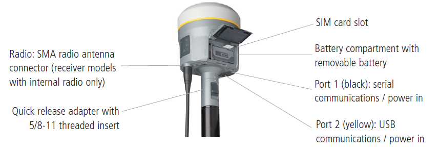
All operating controls are located on the front panel. Serial ports and connectors are located on the bottom of the unit.
Front panel
The following figure shows a front view of the receiver. The front panel contains the four indicator LEDs and the Power button with LED.
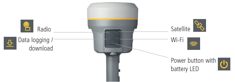
The Power button controls the receiver’s power on or off functions.
The indicator LEDs show the status of data logging/downloading, power, satellite tracking, Bluetooth/Wi-Fi, and radio transmit/receive.
For more information, see Button and LED operations.
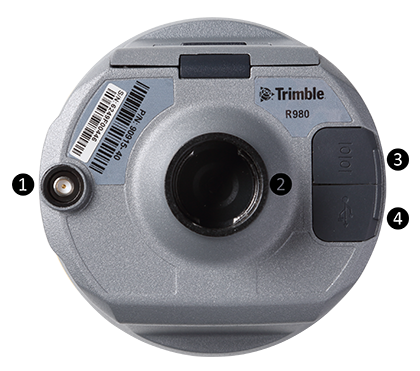
Lower housing
The lower housing contains the two communication and power ports, one
|
|
1
|
|
2 Quick release socket |
|
|
3 Lemo port 1: Serial connection |
|
|
4 Lemo port 2: USB connection |
Receiver ports
|
Icon |
Name |
Connections |
|---|---|---|
|
|
Port 1 |
Device, computer, external radio, power in |
|
|
Port 2 |
Device, computer, USB flash memory stick, power in |

|
RADIO |
Radio communications antenna |
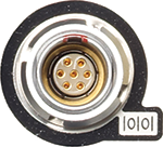
Port 1 is a 7-pin 0-shell Lemo connector that supports RS-232 communications and external power input. Port 1 has no power outputs.
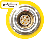
Port 2 is a 7-pin 0-shell Lemo connector that allows for USB 2.0 communications and external power input. For more information, see Default receiver settings.
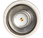
The SMA port connector is for connecting a radio antenna to the receiver internal radio. A whip “rubber duck” antenna is supplied with the system for units with internal UHF radios. This connector is not used if you are using an external UHF radio. For longer range operation (to provide higher gain and to raise the antenna higher above the ground), you can use a cable to connect an external radio antenna to the SMA port.
