Scanning stockpiles
The Stockpile scan is designed to collect very accurate data for reporting on the volume of material that you have or that has been excavated. By scanning the stockpile or excavation, the need to place a worker in potentially unsafe conditions is eliminated. Reflectorless measurement technology enables you to set up the total station and measure to surfaces without using a target or prism.
Given the line-of-sight restrictions when using a total station, you need to perform a minimum of two station setups to collect all sides of the stockpile:
-
From your first setup, measure new control points around the stockpile in locations that will give you the fewest setups and the best vantage points to scan the largest surface area of the stockpile. This enables you to collect all sides of the stockpile and have the surface points correctly related to each other.
-
Once the whole stockpile has been scanned, define a volume boundary in the Cogo menu by tapping the points to be used to define the boundary, or by selecting an existing measured Volume Boundary Line and then perform a volume calculation in the field.
To set up stockpile scanning:
-
From the Home menu, tap Measure and then tap Stockpile Scanning.
-
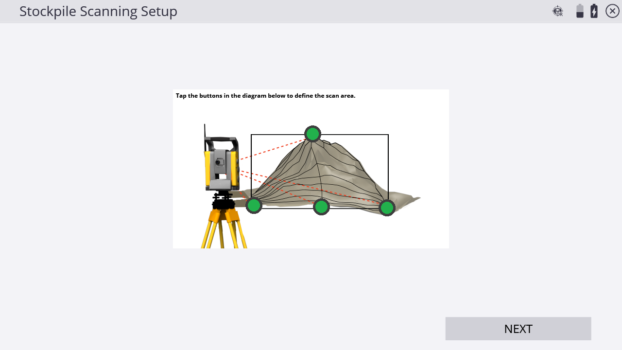
The software sets the instrument to DR mode, and then the following screen appears:

-
Define the shape of your stockpile. Start by tapping the gray dot at the highest point of the stockpile image on the screen.
-
Select a measured or control point by tapping on the screen, selecting it from the dropdown list and tapping Select. Alternatively, manually sight your instrument to the highest point of the stockpile and then tap Measure. The Point Mode screen appears.
-
If required, enter a point code and point name and then tap OK. The Stockpile Scanning Setup screen reappears.
-
Repeat Step 4 through Step 6 to define the bottom left, bottom right, and bottom most points of your stockpile. Once successfully measured, the points appear green:
This feature and the way that the corner points are configured is based on setting the target points on a vertical plane. The lower left and right points set the vertical edges of the plane, and the top and center bottom points define the upper and lower horizontal edges of the plane. If this feature is used at long range, along a gently sloping surface, and/or with a large vertical distance between top and bottom points, it will result in a non-uniform “fan-shaped” spacing of points, as the scan continues to measure points located upwards along the plane, and further from the instrument. This feature is not a substitute for traditional 3D laser scanning methods.
-
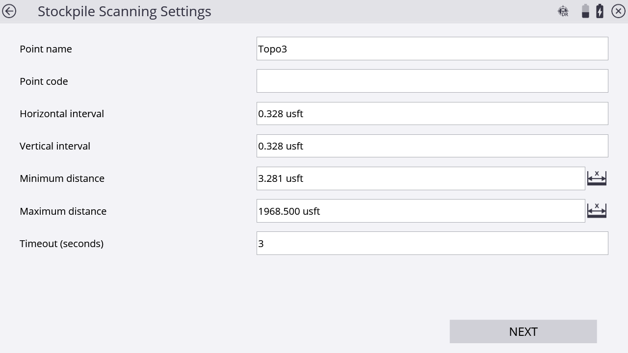
Tap Next. The Stockpile Scanning Settings screen appears:
-
Enter a point name and code and set the horizontal and vertical distance intervals. Setting the distance intervals low results in more measured points; setting the distance intervals high results in fewer measured points. Also, having a smaller interval (more points) will result in a longer scan. When entering these values, keep the size and shape of the stockpile in mind. Define your minimum and maximum distances for point data collection and then tap Next. Correct use of these settings helps you collect only the relevant points in the field on your stockpile. If a point falls outside of these distance values, it will not be measured. Consider setting the minimum distance to be approximately the distance from the instrument to the bottom of the stock pile (closest desired point to be measured), and the maximum distance to be near the top of the stockpile (furthest desired point to be measured). The software will default to the recommended Timeout value depending on which instrument is being used.
-
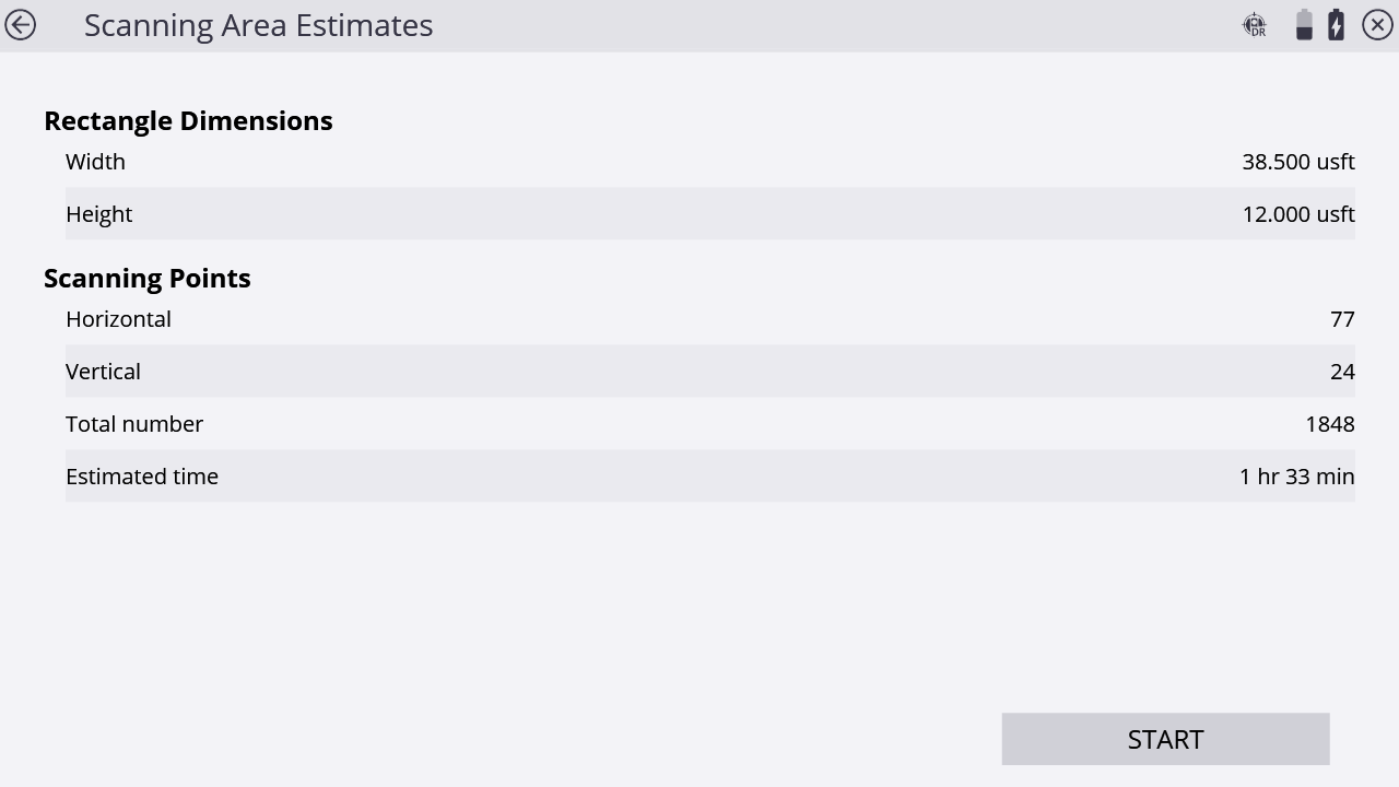
The Scanning Area Estimates screen displays the total number of points to be collected as a result of the dimension and distance intervals previously entered and an estimation of the time it will take to record the points. This time is an estimate only and the reflectivity of the material, distances involved, and the type of instrument used alters the total time once the scan has started.
The values stored in Step 8 are overwritten by the minimum and maximum values set in the DR Target Settings screen. Ensure that you check the values set in the DR Target Settings screen to eliminate confusion by another operator when they are setting the Stockpile Scan settings. Setting the minimum distance to 2 meters (6.56 feet) and maximum distance to 1600 meters (5,249 feet) in the DR Target Settings screen eliminates any errors when setting the Stockpile Scan settings.
When working at the maximum ranges of the DR technology, increase the timeout setting. When adjusting the timeout settings, be aware the material being measured affects the strength of the response signal. The instrument's technology also affects the time it takes to record each individual point.
-
Either tap the back arrow to go back and change any settings before starting the scan or tap Start to start the scan.
-
A grid is displayed as the scan proceeds. Scan time remaining is displayed in the Estimated Time Remaining field. If you need to change the minimum and maximum distance settings, tap Pause and then tap
 . Change the minimum and maximum settings and then tap Next. The scan will resume.
 -
Tap
 in the map control bar on the right to display the map view so you can see the points being collected.
For an explanation of the different grid sector colors, tap
 in the upper right of the screen. The following screen appears:
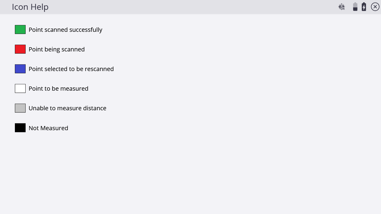
-
To rescan any cells, tap OK to return to the measured cells display. Tap the associated grid sectors with your stylus. Selected sectors turn blue. Once the selection is made, tap Rescan. Repeat the rescan function until results are satisfactory and then tap Finish.
