Info Bar and Info Panel
At the top of the screen is a bar that shows readings and values related to the current operation. There is also an option for an Information panel to be displayed in the Siteworks panels on the map screen. The settings are different depending on the Siteworks mode (Measure mode or Stake mode). The settings are saved independently for both the Information bar and Information panel, and also for Stake or Measure mode.

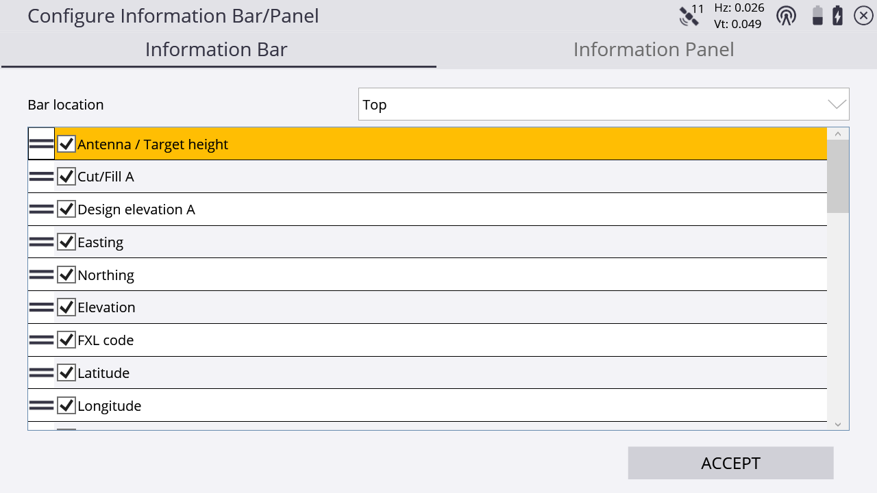
The Information bar can be configured to be displayed at the top or bottom of the screen or hidden all together using the Bar location dropdown list.
Use the arrows on the right and on the left of the Info Bar in the main screen to scroll through the different values which are currently enabled. You can also tap on the bar and "flick" horizontally through the different values. To change the settings, from the Home menu, tap Settings / Info Bar/Panel / Information Bar tab:
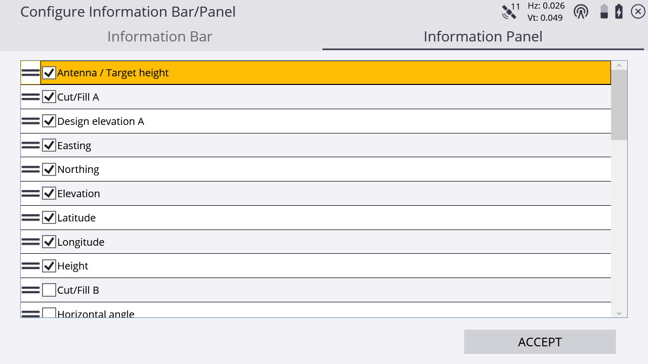
The Information Panel tab changes what is displayed when the information panel is selected to be displayed in one of the panels on the main screen.
The Information panel is separate from the Information bar.
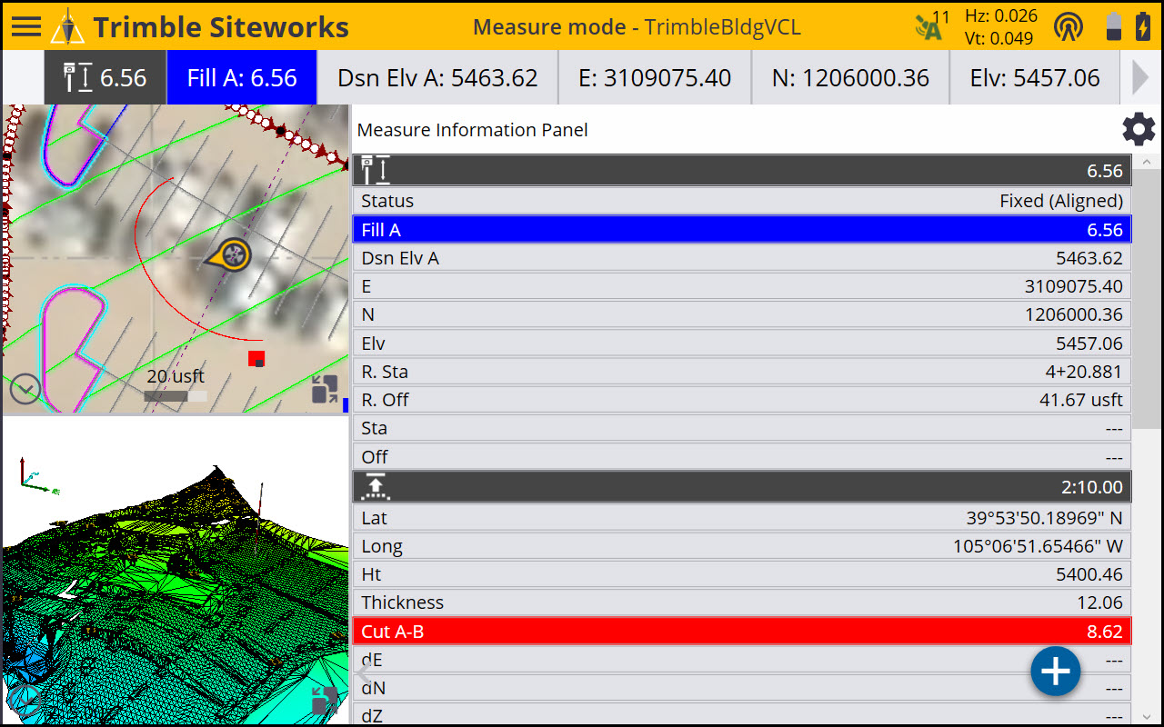
When the Information panel is in the main panel of the screen, the mode of the Info Panel is displayed as either Measure Information Panel or Stake Information Panel. There is also a shortcut to the Info Bar/Panel settings that can be access by tapping the icon ![]() at the top right of the Information panel.
at the top right of the Information panel.
Some fields in the information bar (for example, Antenna/Target Height, Stakeout line offset, and Surface offset) are "active" fields. By tapping on it, you can change the settings and shortcut in the Settings screen of this value. The active fields are indicated by white text on dark gray background.
The following values are available in the Information bar; those indicated with an * are “active” fields:
|
This value… |
shows the… |
|---|---|
|
Ant Ht* |
currently applied antenna height for GNSS. |
|
Tar. Ht* |
currently applied target height for total station. |
|
E |
current Easting in the selected/applied coordinate system. |
|
N |
current Northing in the selected/applied coordinate system. |
|
Elv |
current Elevation in the selected/applied coordinate system. |
|
Horizontal angle |
current horizontal angle the instrument is shooting. |
|
Vertical angle |
current vertical angle the instrument is shooting. |
|
Slope distance |
current slope distance the instrument is shooting. |
|
Lat |
current latitude in WGS-84. |
|
Long |
current longitude in WGS-84. |
|
Stake Distance |
straight line distance from current location to selected stakeout point. This value will not update to individual values of “GO N/S GO E/W” for GNSS when within 2 m of the point, or “Go Farther/Come Near” for UTS (added in v1.70). |
|
Ht |
current height in WGS-84. |
|
Sta |
current station to a selected corridor or alignment. |
|
Off |
current offset from a selected corridor or alignment. |
|
Go |
distance and direction guidance to a selected point or object. |
|
Dsn Elv A |
elevation of the selected primary design, corridor, or alignment at the current location of the user. |
| Dsn Elv B | elevation of the second design surface at the current location of the use. |
|
Thickness |
current vertical thickness of material layer compared to a previous measured layer that has been saved as a design. See Checking material thickness. |
|
R. Sta |
current station to the selected reference alignment or line. |
|
R. Off |
current offset to the selected reference alignment or line. |
|
dE |
difference in East to a selected point or object. |
|
dN |
difference in North to a selected point or object. |
|
dZ |
difference in Elevation to a selected point or object. |
|
Ahead/Back |
difference in station to a selected point along the selected alignment. |
|
Inward/Outward |
difference in offset to a selected point relative to the selected alignment. |
|
Feature B cut/fill |
cut/fill value of the feature node that is created while staking a corridor feature using dual segments. |
|
Feature B design elevation |
design elevation of the second corridor feature created by the dual segments setting. |
|
Dsn Sta |
station to a selected point per design. |
|
Stakeout line offset H* |
currently applied horizontal line offset. |
|
Stakeout line offset V* |
currently applied vertical line offset. |
|
Surface offset* |
currently applied surface offset. |
|
Cut/Fill A |
cut/fill values referenced to the primary surface. |
|
Cut/Fill B |
cut/fill values referenced to the secondary surface. |
|
Design Elv A |
design elevation referenced to the secondary surface. |
|
Design Elv B |
design elevation referenced to the secondary surface. |
|
Cut/Fill between surfaces |
distance between the primary and secondary surface at this location. |
|
Second surface settings* |
surface selection and offset options for secondary surface. |
|
FXL code |
description for the selected feature code. |
|
Bearing |
heading of the receiver relative to True North when Tilt Compensation is enabled. |
|
Pitch |
pitch of the receiver, in degrees, when Tilt Compensation is enabled. |
|
Roll |
roll of the receiver, in degrees, when Tilt Compensation is enabled. |
|
Measured Line Length |
length of line being measured; only includes measured points. |
|
Total Line Length |
length of line being measured; includes segment from last measured point to user’s current location. |
|
Last Segment Length |
length of line segment from last measured point to user’s current location. |
|
Last Segment Slope |
slope of segment from last measured point to user’s current location. |
|
Measured Line Area |
area of line being measured, only includes measured portions of line. |
|
Total Line Area |
area of line being measured including segment from last measured point to user’s current location. |
|
GNSS Hz Precisions |
horizontal GNSS precisions. |
|
GNSS Vt Precisions |
vertical GNSS precisions. |
|
RTK Status |
current GNSS fix status. |
|
Attachment Selection |
current attachment selection when in Machine Guidance mode. |
|
PDOP |
current Position Dilution of Precision. |
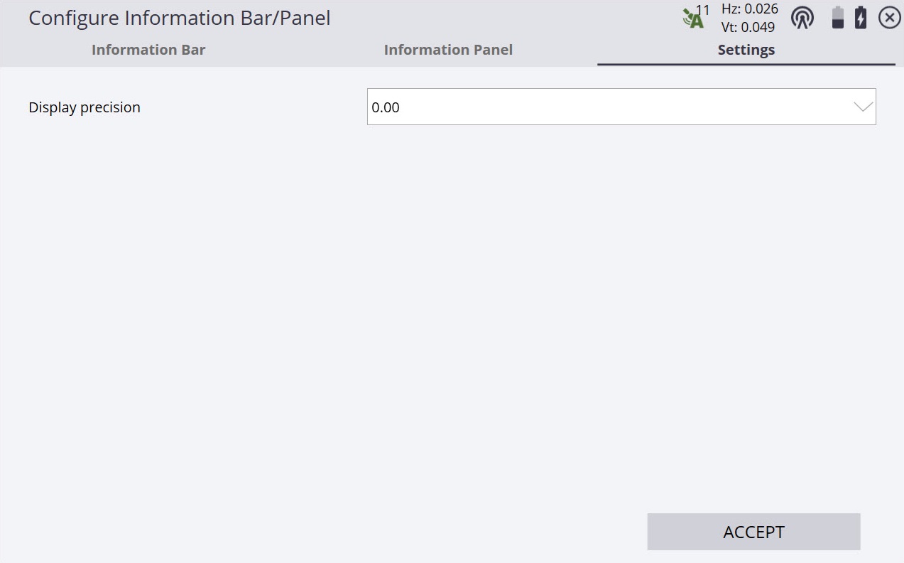
Use the Settings tab of the Configure Information Bar/Panel to set the number of decimal places to be displayed in the Information bar and panel. This is a display-only setting and all measured values are still stored at full precision.