Calibrating the site
Global Navigation Satellite Systems (GNSS) produce positions in latitude, longitude, and height coordinates. Construction projects are generally designed in northing, easting, and elevation (or X,Y,Z) Cartesian coordinates. A project calibration ties the GNSS positions to the local site coordinate system so that GNSS can be used to measure or stake out on the construction site. The project calibration process involves measuring several known control points in the local site coordinate system using a GNSS rover, allowing the software to create pairs of measured latitude, longitude, height, and known control points.
To calibrate the project:
-
From the Home menu, select Project Setup and then tap Project Calibration.
-
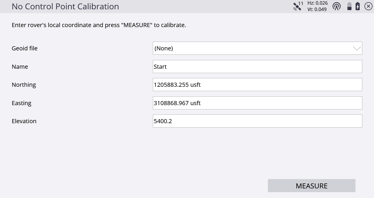
If you have no control points in your project, you are prompted to enter a coordinate for where you are standing. The software computes a one-point calibration based on this coordinate and will be oriented without any rotation so that the project’s local north direction will be true north:
-
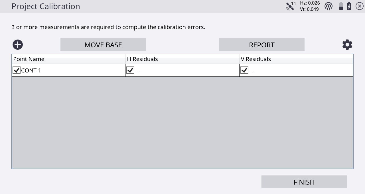
If control points exist in your project, you are prompted to select a control point and then measure the physical point on the ground with your rover receiver. To add a calibration point in the Project Calibration table, tap the plus icon:
 .
.
-
When enough control points have been measured, horizontal and vertical residuals will appear on the screen.
-
To change any of the calibration settings, tap
 to open the Calibration Settings screen. Here you can change various settings relating to the calibration such as the horizontal and vertical tolerances for the residuals, the number of points to compute an inclined plane (or set to Never to not compute an included plane), and if you want to set the calibration scale factor to 1.
-
If the residuals displayed in the calibration table are acceptable, tap Finish to end the calibration. The calibration is then used for the project.
The project calibration is stored in a DC file that can be used with other Trimble equipment working on the project. The software can also export the project calibration as a CFG file for use with Trimble GS900 or as a CAL file for use with Trimble Earthworks machine control systems.
The software notifies you after three points have been measured whether the calibration is in or out of tolerance with respect to the calibration tolerances. After each point you have the following options:
-
measure additional points
-
retake a point flagged as potentially in error
-
save the partial calibration and resume later
The danger of using residuals as the only means of controlling a calibration is that the best precisions can be achieved using the wrong combination of points in the calibration solution. When an inclined plane is in use, this manipulation of residuals can result in a steeper tilt of the plane to best fit the data, resulting in better precisions and an in-tolerance calibration. Monitor the tilt of the plane closely, especially when the geometry of the control points is not strong. Widespread control that covers the entire site is good; narrow-based control around a corridor is not as good. An incorrect tilt of the plane can result in increasing errors in height as you move away from the center of the controlled area.
Once a project calibration is performed and completed, you cannot change or add to the calibration in that project. To add points to a completed project calibration, start a new project and import the existing DC file from the project which you want to add control points to.
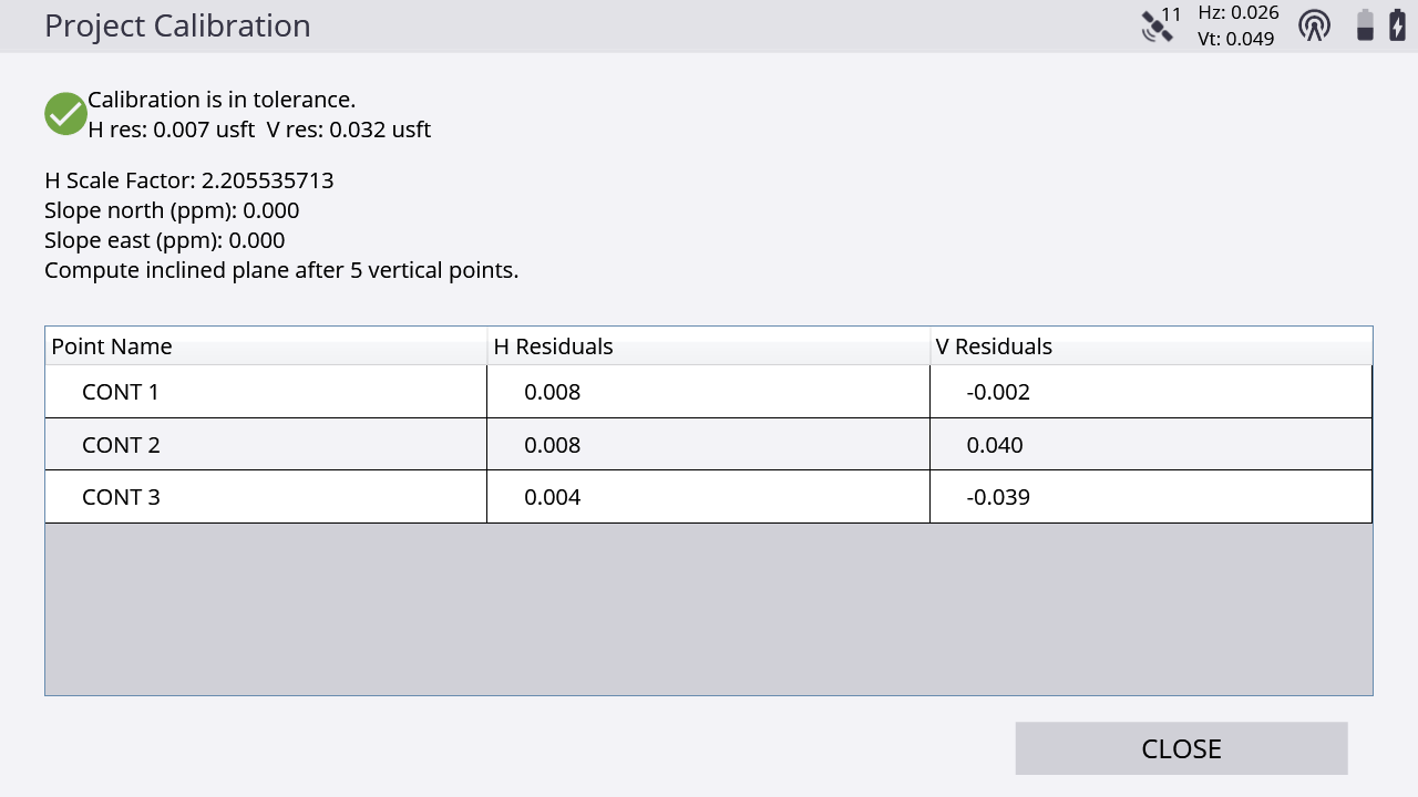
You can review a project calibration completed in Siteworks by tapping the Home / Project Setup / Project Calibration. You are prompted if you would like to review the calibration report. Tap Yes to show a table showing the calculated scale factors, point pairs, and residuals:
Tap again in the table to activate the table and enable you to turn off/on individual points, to see the effects on the residuals and scale factors. Note however that this is a display-only feature, therefore any changes made in the Project Calibration Review table are not saved, and the calibration will not be affected.
Performing a two-point calibration
Trimble recommends that wherever possible you use a multi-point calibration of at least three points. Use the two-point calibration method in situations where a baseline of only two control points is available. In the two-point calibration, the first point establishes the position and elevation for the project; the second point establishes the project orientation.
In a two-point calibration, the heights for the project are computed using a simple block shift method that ties all heights to the first measured control point. A two-point calibration is carried out in the same way as a multi-point calibration.
Troubleshooting a site calibration
If a project calibration fails repeatedly, try the following solutions:
-
Try a different combination of control points. The software cannot always identify the bad point.
-
Start the calibration process again. You may have incorrectly measured a point or points.
-
Check the equipment. The source of the error may be as simple as the adjustment of the rod bubble, or a bent rod.
Once the system is setup, there are limited sources of error when using RTK GNSS systems. The most common sources of error include:
-
A poor project calibration
-
Incorrect base antenna height
-
Incorrect rover antenna height
-
Incorrect selection of the correct antenna type at the base or rover, which causes height errors
-
Incorrect location of the base station antenna
-
A GNSS rod bubble is out of adjustment or the rod is bent
These errors can easily be detected by rechecking the system setup. After starting the rover each day, the software prompts you to recheck the system setup. All recheck system setup operations are logged in the work order report and record files for reference and troubleshooting requirements.
To turn off the prompt for a system recheck, open the managers menu (tap Ctrl+O (letter “oh”)). You can also turn off the prompt to adjust a published coordinate system with a site calibration.
