Corridor feature staking
-
From the Measurement screen, tap the Home menu / Stake.
-
Select a corridor or alignment using the list at the top right of the screen and then select an alignment in the Road tab. In the Stake Method dropdown menu, select Feature and click ACCEPT.
-
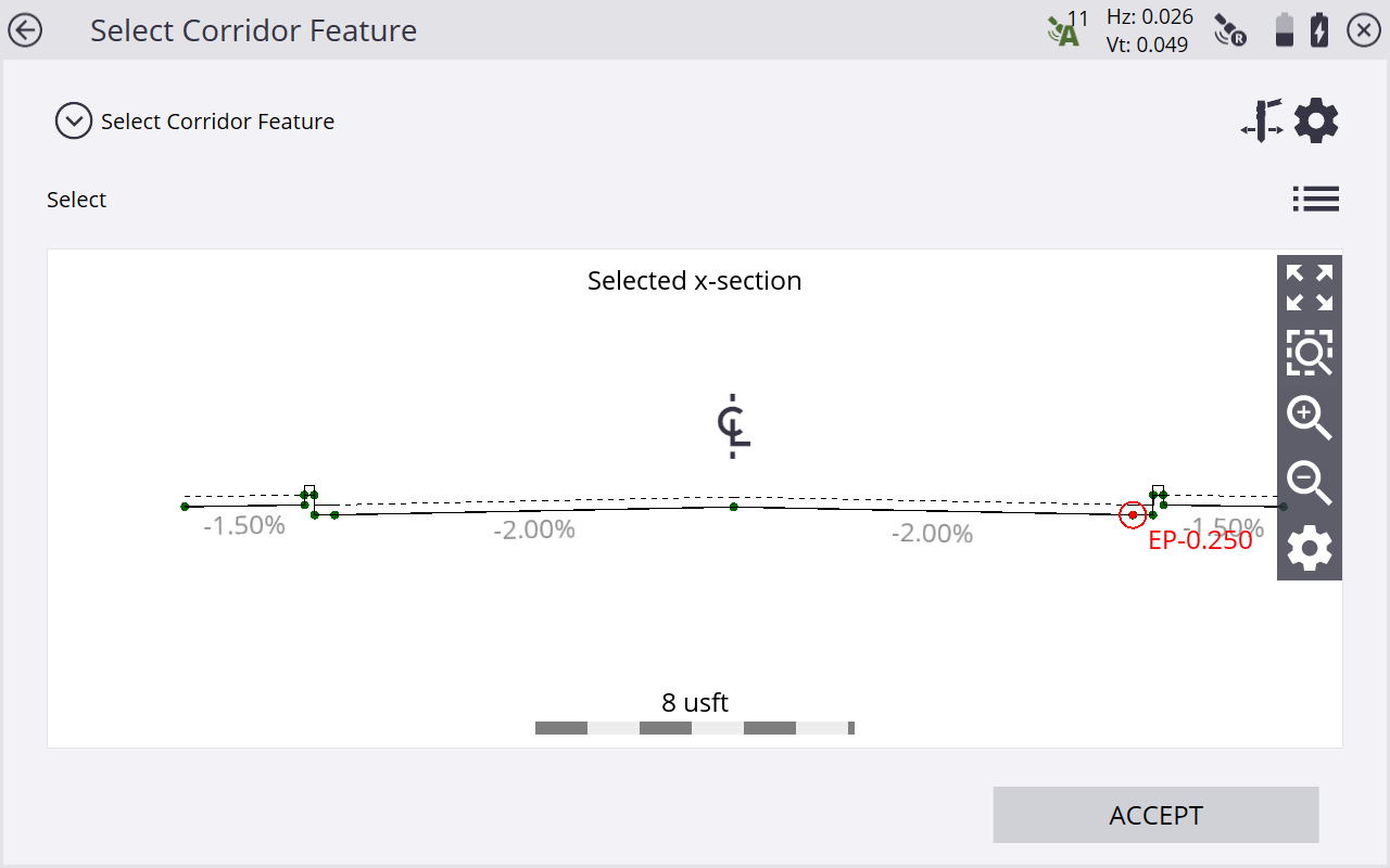
Enter a station or select one from the map at which to stake out the corridor feature. The Select Corridor Feature screen appears. A cross section of the corridor notes the location of each roadway feature as a node on that cross section.
-
Select the corridor feature node that represents the corridor feature that you want to stake out. To select a node, do one of the following:
-
Select from a node list (tap in the top right corner).
-
Tap the required node.
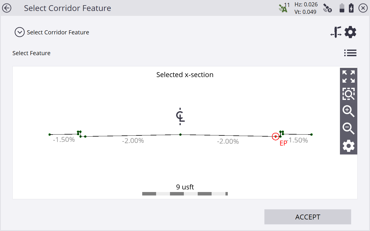
If the node is on the finished grade model, the name of the node would be EP, for example. If the node being selected is on the subgrade adjusted surface, it would be named EP-0.250; meaning it is the EP node, but it has a -0.250 m offset. A subgrade can be entered by accessing the corridor settings through Settings / Corridor or by tapping the Corridor settings icon on the upper right side of the screen and entering a subgrade offset value.
If you are navigating up station, the normal cross section view is displayed left to right as expected. If you are navigating down station, then the cross section would normally be back to front. To reverse the view of the section, select the Home menu / Settings / Roads, and change the view setting to up station or down station.
-
-
Let the software guide you to the point to be staked on the selected feature using the values in the info bar. To help you find the point, the guide arrow needs to point up the screen to show that you are traveling directly toward the point. You can turn the guide arrow off and on in the Design tab of the Map Options screen. The information bars at the top of the screen can be customized using the Info Bar/Panel option in the Home menu / Settings. By default, the info bar shows the design elevation for the point, the amount of cut or fill required to get to that elevation, and how far and in what direction you need to travel to get to the point. You can scroll through the different values using the gray arrows on either side of the info bar. The default map view has the direction north pointing up. To change this so that the direction you are walking is pointing at you, change the map rotation in Map Options screen. You can turn on a cut/fill lightbar in the top or bottom panels on the left to graphically show the cut and fill.
-
When you are close to the stakeout point, the software switches into the Fine Stake mode. Additional guidance arrows appear on the top right corner of the map to indicate the remaining distance in each direction. The screen is oriented to the last moving direction before the Fine Stake mode was activated if map rotation in travel direction was selected.
-
When staking with a GNSS, the fine navigation arrows are displayed in a north "up" orientation or based on the direction of approach when the fine stake arrows first appear. Change this behavior with the Stakeout Guide option in the Design tab of the Map Options screen.
-
For staking performed with a total station, the fine navigation arrows are oriented depending on the connection method to the total station.
-
For Bluetooth and cable connections, the directions are as if you were standing behind the total station looking towards the point or prism.
-
For radio connections, the directions are as if you were standing at the prism pole looking towards the total station.
-
-
After tapping the Measure icon, a stakeout report appears. The software creates a Stake Marker report, including the Cross-Section Storyboard to write on the stake in the Report tab. A graphical diagram shows how to put an elevation mark on the stake. The software does all the calculations for you. The way that the software calculates the elevation mark and cut/fill depends on the stakeout settings in Settings / Stakeout. The software remembers which tab of the stakeout report was last viewed and opens the same tab after staking the next point.
Instead of staking a certain station, you can also stake an alignment at random stations using these buttons on the bottom right of the status bar:
Tap…
to…

stake at fixed intervals starting at a certain station.

stake at random intervals somewhere along the alignment, based on the perpendicular location from the centerline.
-
Set the Auto advance option field to one of the following options using the Corridor Settings screen. From the Home menu, select Settings / Corridor, or tap
 :
:To…
select…
automatically move to the next station.
To next station.
automatically move to the previous station.
To previous station.
manually move to the next or previous station.
No.
This option maintains the current station between points and enables you to increase or decrease the station when you are ready.
not move a station.
Depending on the settings for Station Interval, the Siteworks software will or will not advance to the next station.
-
To set whether the next auto-advanced station will be on a tangent point in the Horizontal and/or Vertical Alignment of the corridor, in the Tangent Point option:
Select…
to…
Horizontal only
stop at Horizontal tangent points.
Vertical only
stop at Vertical tangent points.
Horizontal and Vertical
stop at Horizontal and Vertical tangent points.
None
not stop at any tangent points.
