Using Tilt Compensation
Enabling Tilt Compensation
There are two ways to turn on Tilt Compensation:
-
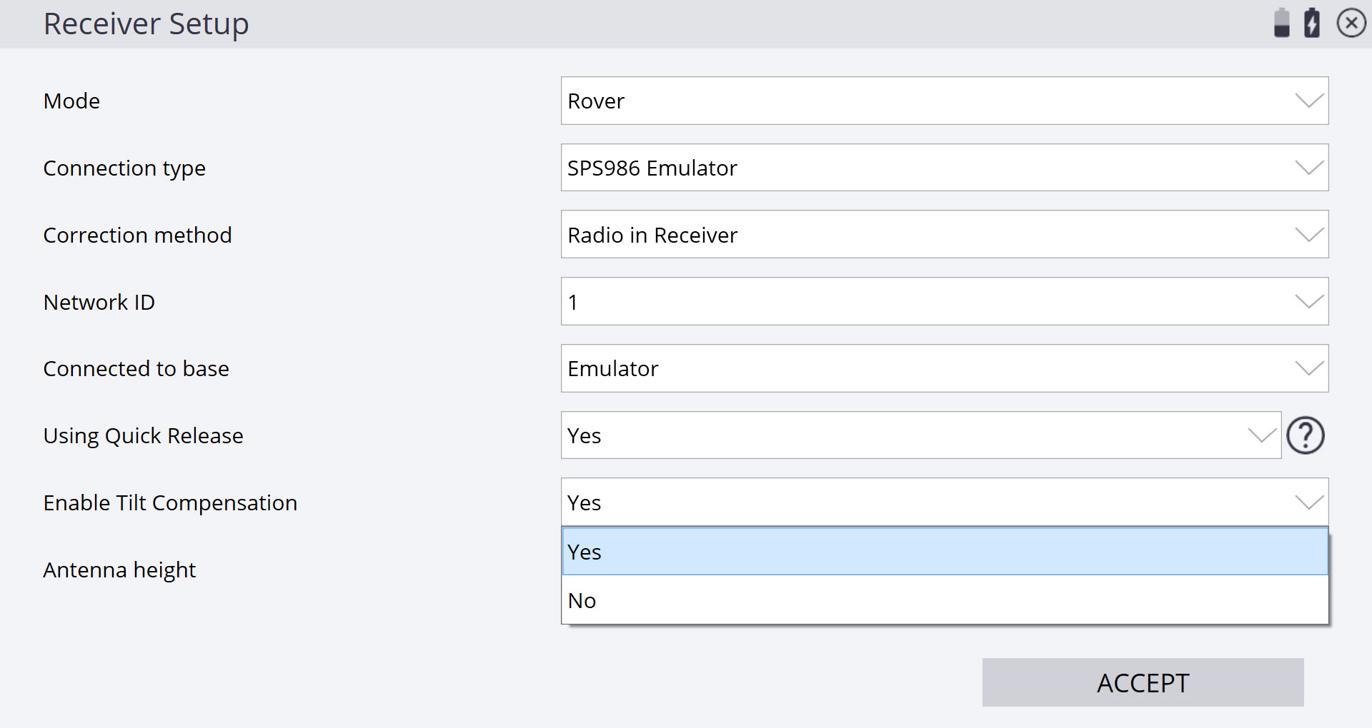
During receiver setup in the Receiver Setup screen.
When connected to an SPS986, R780 or other Trimble tilt-enabled receivers GNSS smart antenna with the required INS option code installed, the Enable Tilt Compensation option becomes available. Select Yes to activate Tilt Compensation during the receiver setup process.
-
In the main working screen.
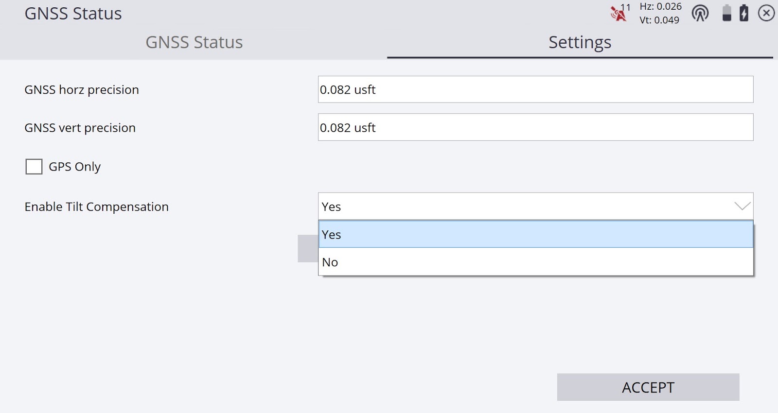
You can enable Tilt Compensation in the GNSS Status screen. Tap the GNSS icon or current GNSS precision in the top right corner of the Siteworks screen. Then in the Settings tab, select YES from the Tilt Compensation dropdown list.

Icons and GNSS precision values
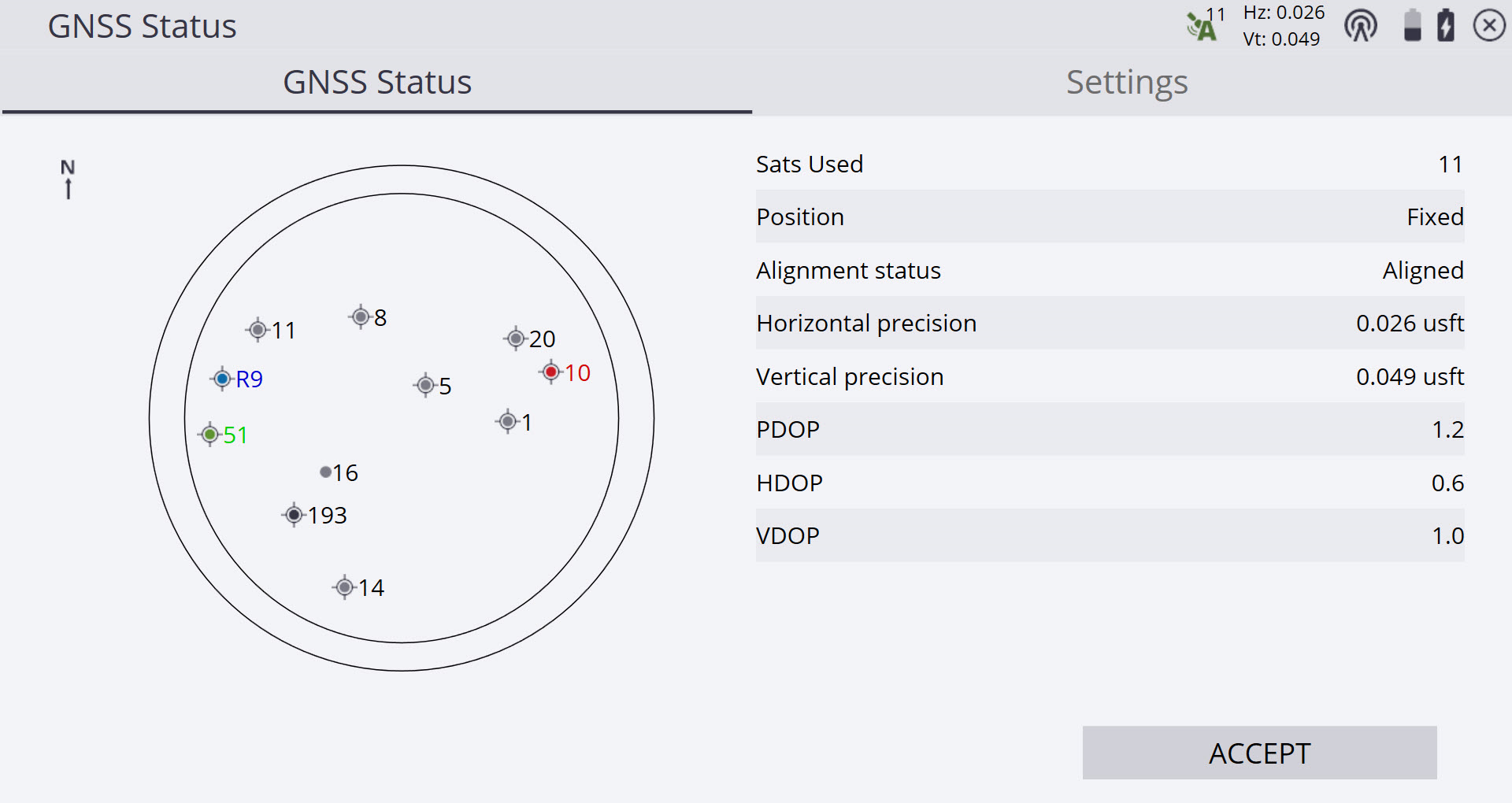
When Tilt Compensation is active, an alignment status symbol appears in the top right corner of the Siteworks screen. The symbol displays the number of connected satellites and the alignment status. Next to this are the current precision values. The precision values are calculated in real time and account for the number of satellites, current DOP, the quality of the alignment and the tilt of the receiver. Precision values displayed are at the pole tip when Tilt Compensation is active. In GNSS-only mode without Tilt Compensation, the precisions are calculated at the Antenna Phase Center. Generally, the more a receiver is tilted, the larger the precision values become.
Desired precision tolerance values are set in the GNSS Status / Settings tab to prevent recording a value outside of the tolerances. As in GNSS-only mode, once the precision values exceed the input tolerances the info panel and info bar flash red until the precision values drop below the tolerances.
When Tilt Compensation is enabled, the following icons display the status of Tilt Compensation.
|
Symbol |
Description |
|---|---|
|
|
Receiver is not aligned, measurements are not corrected for receiver tilt. No precision values are displayed when the receiver is not aligned in standing and walking mode. |
|
|
Receiver is aligned, measurements are corrected for receiver tilt. Precision values are only displayed when the receiver is aligned. |
|
|
Receiver is not aligned. The Siteworks software does not know the direction the receiver is orientated. |
|
|
Receiver is aligned. The arrowhead displays the direction the receiver is facing in relation to the Site Bearing (that is, the local north of the project). On the SPS986 or R780 GNSS smart antenna, the front panel needs to be facing the user for this to be orientated correctly (same as the eBubble). |
The receiver alignment status is also displayed in the GNSS Status screen:
Correction methods available with Tilt Compensation
Tilt Compensation can be used with the following correction methods:
-
Radio in Receiver
-
IBSS
-
Internet (VRS)
-
External Radio
-
Wi-Fi
-
Centerpoint® RTX correction service over satellite and internet
Base station setup is not supported with tilt compensation.
Measurement modes available with Tilt Compensation
Tilt Compensation can be used with the following measurement methods:
-
Standing
-
Walking
-
Vehicle
The following features are not available when tilt compensation is active: Static measurement mode and EZ level. Measure control points, recheck system, Bench My Rover routine, and project calibration are not supported in Tilt Compensation mode as they use the static measurement mode.
Siteworks version 1.60 added a new option to toggle off Tilt Compensation when a static measurement is taken. A prompt asks you if you want to temporary disable Tilt Compensation. Tapping YES at the prompt will turn off Tilt Compensation during the static measurement and re-enable it when changing measure modes from static. Tapping NO will return you to the main map screen.
Standing and walking modes


Standing and walking modes are designed to be used with pole-mounted receivers. By tilting the pole or walking a few steps (generally less than 3 m) to measure the first point, the receiver will be aligned and ready to record measurements without needing to level or plumb the pole.
To correctly orientate the internal hardware components and the eBubble on the Siteworks screen, ensure that the GNSS receiver faceplate on the pole is pointed toward you.
Vehicle mode

Vehicle mode is designed to use with vehicle-mounted receivers. Alignment occurs by driving the vehicle for a short distance. Alignment can be achieved most rapidly by driving in a circle or with multiple direction changes. As in regular vehicle mode, points are measured at either defined horizontal and vertical distance intervals or at defined time intervals.
Vehicle mode uses a different internal kinematic model within the receiver than walking mode, leading to better results in vehicle-mounted applications. Therefore, it is recommended to always use Vehicle mode with a Tilt Compensating receiver when it is to be used on a vehicle.
When mounting the GNSS receiver on the vehicle, ensure that the faceplate is pointed toward the rear of the vehicle. This ensures correct orientation of the internal hardware components and the eBubble on the Siteworks screen. Trimble recommends that the receiver is mounted on the vehicle in a rigid location that is least likely to be subject to deformation and vibration as it allows the antenna height to be as consistent as possible and minimizes excess vibrations to the IMU sensors. Placing the receiver near the engine compartment of the vehicle is not recommended due to excessive vibration. Examples of good mounting locations are over the rear wheels of a truck, or on an overhead rack. The receiver should also be mounted in as level a position as possible on the vehicle (that is, not on a steeply sloping hood or roof). If the receiver is mounted at an angle while the vehicle is on a flat surface, vehicle mode measurements project the tilt of the receiver to calculate the position of the “virtual rod tip” as if the receiver were on a tilted survey pole and not directly under (or vertically plumb to) the receiver.
A Tilt-Compensated vehicle mode was previously available in Siteworks version 1.02 and 1.03. In these versions of Siteworks, vehicle mode was called Dynamic Tilt. The SPS986 receiver required firmware version 6.00 or later to use Dynamic Tilt. In Siteworks version 1.10 and later, Dynamic Tilt has been changed so that it is activated as vehicle mode when Tilt Compensation is on. Using any Tilt Compensation features in Siteworks version 1.10 or later requires GNSS firmware 6.01 or later to be installed on the SPS986, R780 or any other Trimble tilt capable receivers.
Displaying and storing tilt data
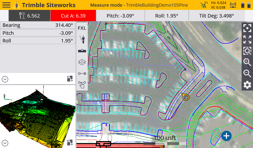
When Tilt Compensation is enabled, the current bearing, pitch, and roll of the receiver can be turned on in the information panel and information bar. The Bearing is the direction of the receiver relative to True North. The Pitch and Roll display the tilt of the receiver on the X and Y axis. These values are always displayed in degrees regardless of the user’s settings.
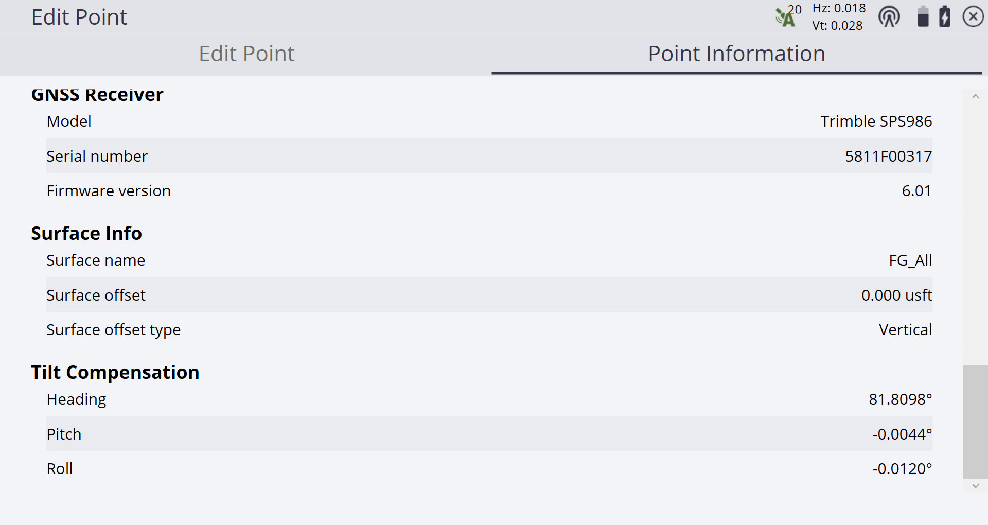
When a point is measured in Tilt Compensation mode, the bearing, pitch, and roll of the receiver at the time of measurement can be viewed in the Point Information tab. This is displayed under the Tilt Compensation section. The Tilt Data section is obtained from the eBubble. The eBubble data is independent of the Tilt Compensation data. For example, if the eBubble is calibrated or “zeroed” while tilted, the “Tilt Angle” will be zero, but the pitch and roll will represent the amount of pitch and roll at the receiver relative to a flat surface.
Additional quality assurance data is contained for points measured with Tilt Compensation when a CSV file is exported. From the Home menu, select Data Management / Export Measured Data). Ensure the Include QA data option is set to Yes. The heading, pitch, roll values are exported along with the Antenna Phase Center and the latitude, longitude, and height of the pole tip.
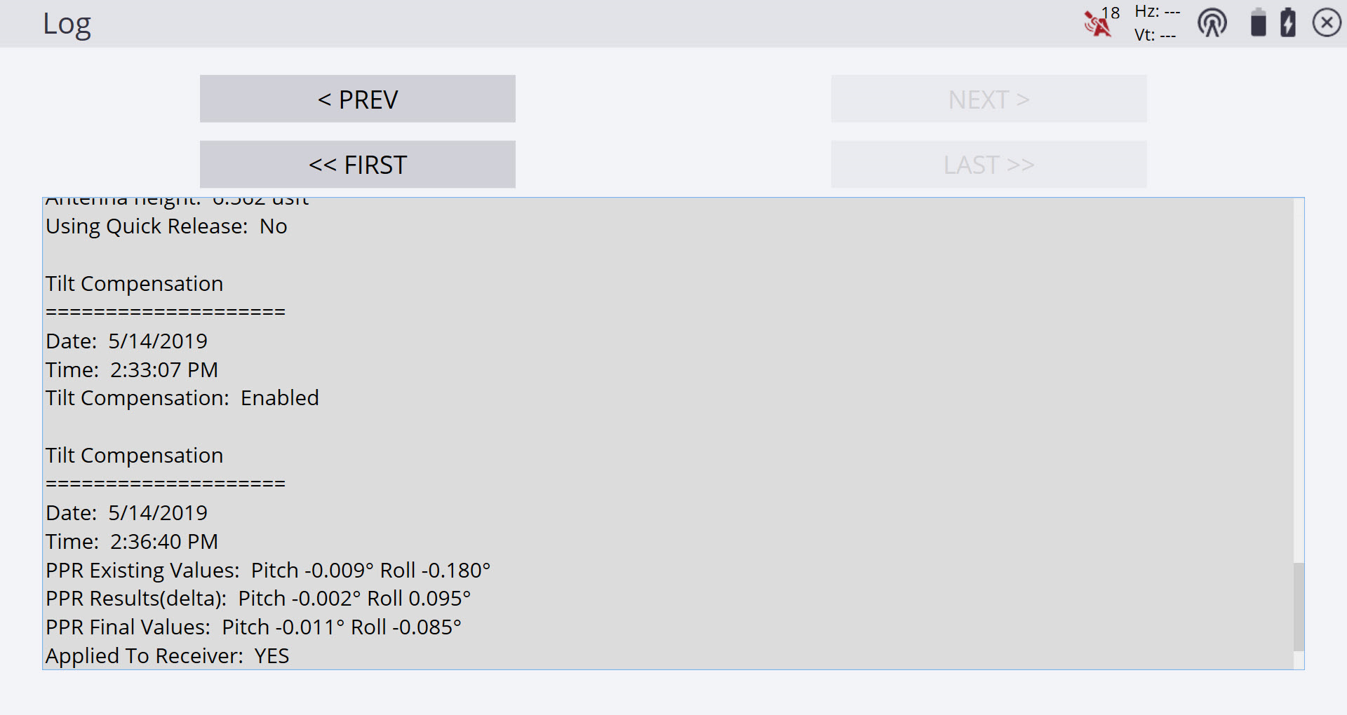
Log file
When Tilt Compensation is enabled or disabled, a new entry is made in the task log. Whenever the Plumb Pole routine is run this data is also stored. To view the log, select Home menu / Data Management/ Log.
Emulator and Tilt Compensation
The emulator supports Tilt Compensation. In the receiver setup, select the SPS986 Emulator. The receiver is not initially aligned. Click on two locations in the main map screen to change the receiver position; the emulator will change to aligned mode.
eBubble and Tilt Compensation
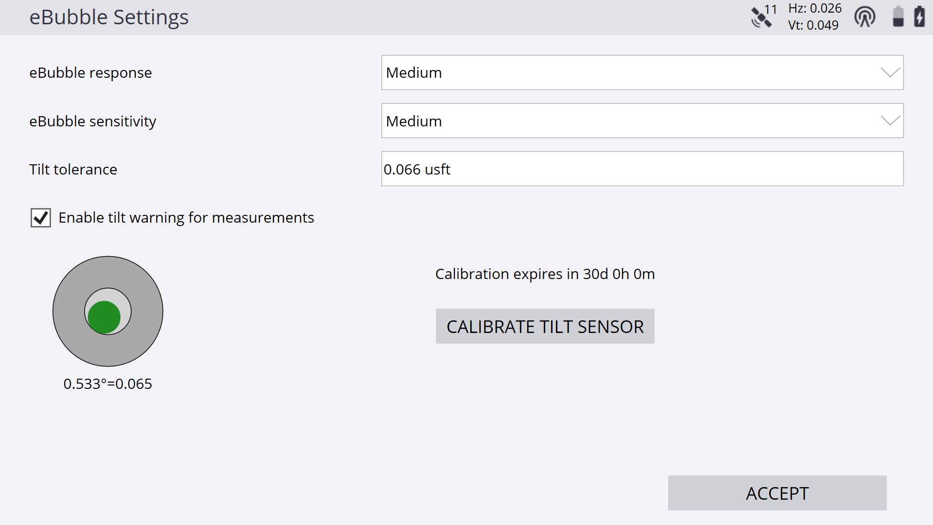
By default, the Enable tilt warning for measurements checkbox is turned off when starting Tilt Compensation, so that Siteworks does not display a tilt warning message while taking measurements when the receiver is tilted. To enable or disable this warning, tap the eBubble icon on the Siteworks main screen or from the Home menu, select Settings / eBubble:
The eBubble operates independently of the IMU sensors used in Tilt Compensation. Calibrating the eBubble to “zero” while it is tilted (for example, on the sloped roof of a vehicle parked on a flat surface) has no impact on the IMU sensors and measurements in Tilt Compensation. If the receiver is mounted at an angle while the vehicle is on a flat surface, Tilt Compensation measurements still project the tilt of the receiver to calculate the position of the “virtual rod tip” as if the receiver were on a tilted survey pole and not to a point directly under (or vertically plumb to) the receiver. To obtain the most accurate results while operating in vehicle mode, mount the receiver as level as possible on the vehicle.
