Tilt Compensation workflow
Select measurement mode
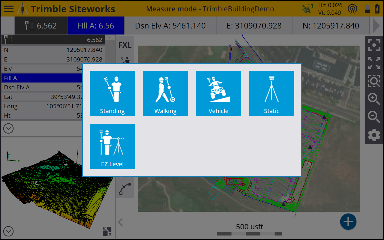
Once Tilt Compensation is turned on, select the required measurement mode. If a measurement mode is not selected, the default is Standing mode. Note the difference in the icons when Tilt Compensation is enabled versus when it is disabled. The Tilt Compensation icons show a tilted rod or vehicle.
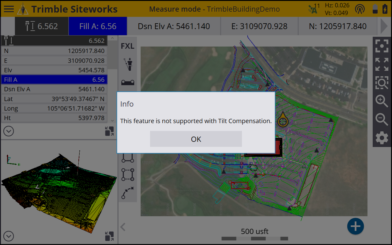
If an unsupported measurement mode is selected while Tilt Compensation is active, a warning message appears:
Standing and walking mode workflow
-
From the Measurement Mode menu, select Standing or Walking.


-
Ensure the antenna height is correct. For best results when using Tilt Compensation, Trimble recommends that you do not use the quick release.
It is very important that the pole height is correct when Tilt Compensation is turned on; it is no longer possible to correct data with a wrongly entered pole height by simply modifying the Z (height) value of the points to correct the error. Changing the pole height in the Point Manager or in the Trimble Business Center software only vertically shifts the point’s elevation; it does not take into account any tilt of the pole at the time of measurement. This could lead to horizontal errors in the point if there was a large amount of tilt at the time of measurement.
-
Tilt Compensation uses the antenna height to accurately compute the pole tip position. Whenever the pole height is changed, the receiver is reset to an unaligned state. You will need to realign with the updated pole height before measuring.
-
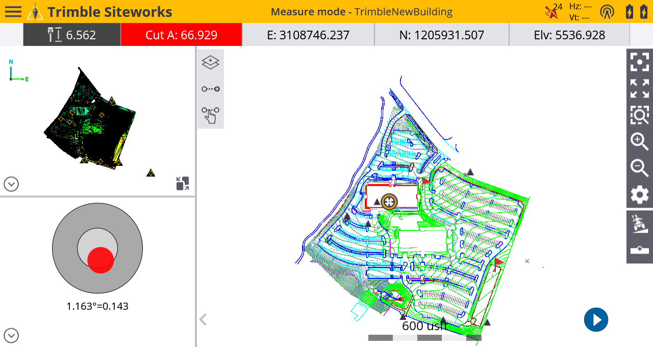
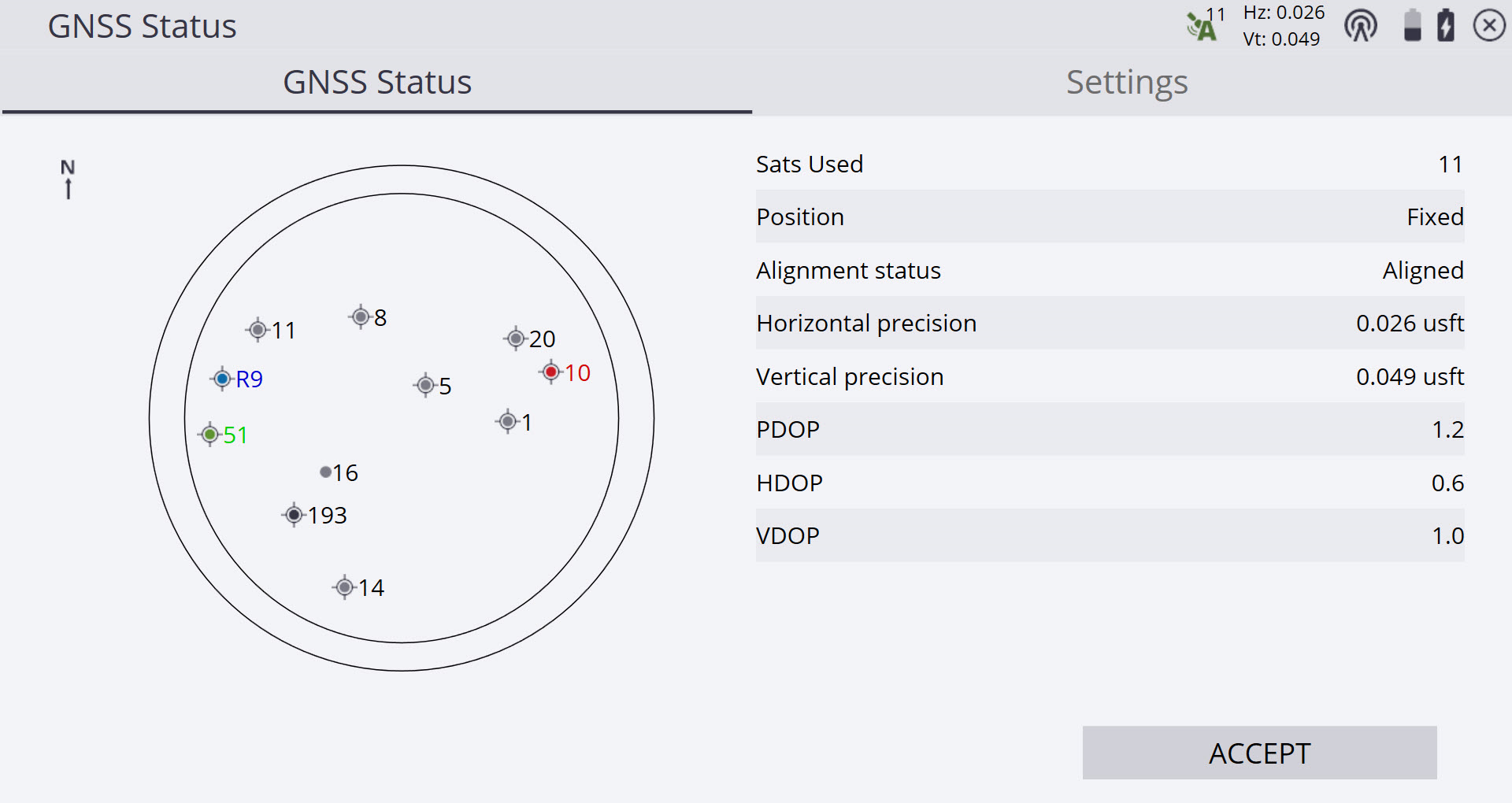
Once back in the main map screen the receiver now can be aligned. To align the receiver, make minor movements such as tilting the pole or walking a few steps to measure the first point. The alignment symbol turns from red to green and the GNSS precision will be displayed. Alignment status is also displayed in the GNSS Status screen / GNSS Status tab by tapping on the alignment symbol. The Alignment Status line in the Skyplot screen displays the current state of the receiver’s alignment.
-
Once the receiver is aligned it is ready to take tilted measurements. The GNSS precisions reflect the accuracy of the alignment and the precision calculated at the pole tip. The horizontal precision value generally becomes larger the more the pole is tilted.
-
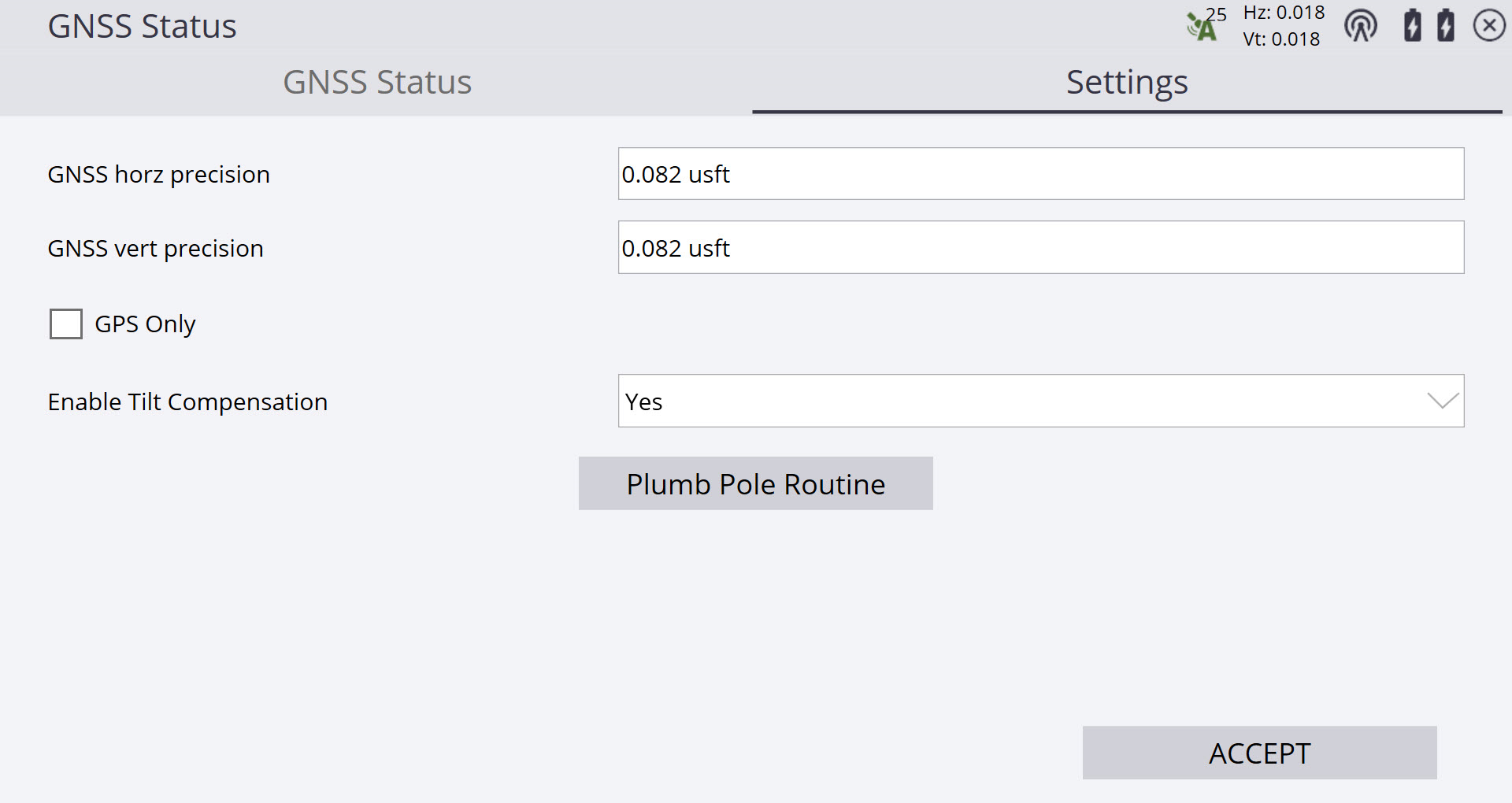
Set the required precision values to prevent recording a value outside of the tolerances. To set this, tap on the GNSS precisions in the status bar in the top right corner of the main screen. Select the Settings tab and enter the horizontal and vertical precision. The precision values and info panel/bar flashes red on the map when outside of these defined tolerances.
If the GNSS loses its correction stream (e.g., the VRS connection is dropped or base station radio disconnects), the receiver will go into xFill mode for up to 5 minutes. During this time, you can continue to take measurements. Once xFill quality has deteriorated and the xFill fix is no longer valid, the receiver will switch to Autonomous mode. In this mode, the precisions displayed will be dashed out and no measurements can be taken.
Vehicle mode workflow
-
Ensure the vehicle is stopped and parked in a safe location.
-
If Tilt Compensation is not on, activate it through the GNSS Settings screen.
-
Once the receiver has been mounted to the vehicle, tap the measure mode icon from the quick access toolbar on the lower right side of the plan view map window, or from the Home menu, select Settings / Measure Mode.
-
From the Measurement Mode menu, select Vehicle. The tilted slope of the icon shows that Tilt Compensation is active.

The vehicle must be stationary during the activation of vehicle mode to enable the IMUs to be correctly initialized.
-
Update the height of the receiver in the Vehicle Mode Settings screen to reflect its mounted position on the vehicle. To do this, use a measuring tape or park the receiver above a point of known elevation.
-
To set the height by parking the vehicle over a known elevation, Tilt Compensation must be turned off. Return to the main map screen, turn off Tilt Compensation and then select the vehicle measure mode again. Park the vehicle on a level surface over the known elevation point and select the Measure antenna height icon.

-
Select either a control point or manually enter the elevation of the ground surface below the antenna. Tap Measure. The antenna height has now been measured relative to the ground surface elevation. Turn Tilt Compensation back on and re-enter the Vehicle Mode Settings screen to complete the configuration.
-
Alternatively, measure the height of the receiver to the bottom of the quick release (if using) or the bottom of the receiver by using a measuring tape or other method and manually enter the antenna height. Tap the ? icon for a graphic showing the correct antenna height measurement point.
-
To change a height measured with a tape measure, tap the antenna height in the information bar. Each time the antenna height is changed, the receiver must be re-aligned.
-
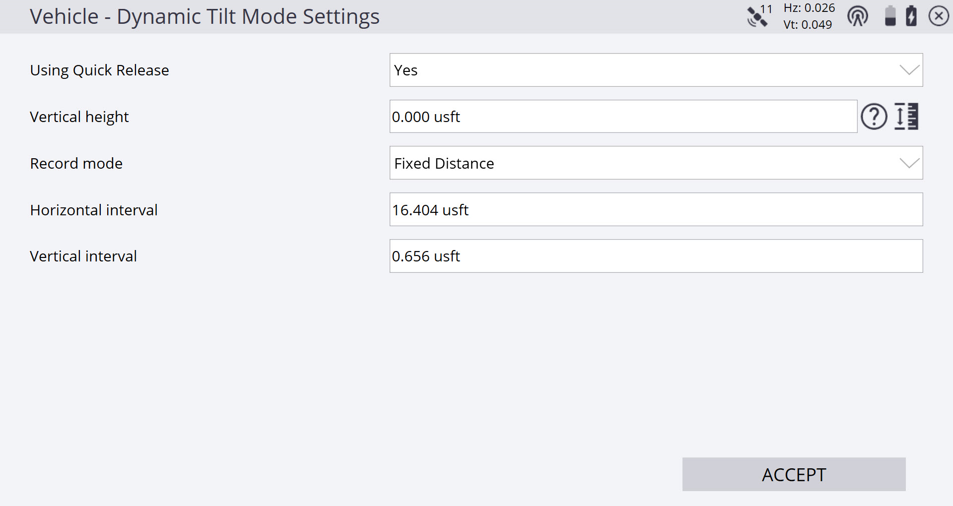
Select a recording mode:
-
Fixed Distance – Enter horizontal and vertical intervals; a point is automatically stored each time the vehicle moves the defined distance.
-
Fixed Time – A point is recorded at the defined time interval.
-
Tap Accept to start vehicle mode and return to the main map screen.
The vehicle must remain stationary for 30-45 seconds after returning to the map screen for the IMU sensors to initialize in a non-moving state before beginning the alignment process. Moving the vehicle before this sensor initialization may prevent a successful alignment.
-
-
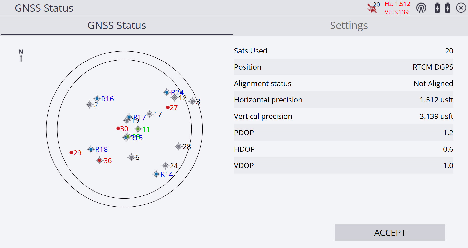
Remain stationary for at least 30 seconds to ensure that the GNSS + INS engine has reset successfully, and the receiver is not in RTCM DGPS mode. Trimble recommends waiting for the position status to change to Float. This can be confirmed in the GNSS Status (skyplot) screen by tapping on the alignment symbol/GNSS precisions and waiting until the position is no longer RTCM DGPS (it should read “Float” or “Autonomous”).
-
You must now align the receiver by driving the vehicle. Alignment completes the initialization process of the IMU sensors to achieve high precision positions. Drive the vehicle until the alignment symbol turns from red to green and displays the precision within defined tolerances. Driving in a circle or with direction and speed changes can achieve alignment faster than driving in a straight line. Alignment status is also displayed in the GNSS Status screen / GNSS Status tab accessed by tapping on the alignment symbol. The Alignment Status line in the Skyplot screen displays the current state of the receiver’s alignment.
If alignment cannot be obtained after driving for more than one minute, stop the vehicle and open the GNSS Status (Skyplot) screen. Check the Position status to ensure it is not in RTCM DGPS mode. If RTCM DGPS is still active, remain stopped until the Position status changes to Float or Autonomous before driving again.
-
Returning to Siteworks’ main map screen, select the Measure Type icon from the quick access toolbar. Define the point or line type to be collected and return to the main map screen to begin measurements.

-
To start recording measurements tap the “play button” in the main measurement screen. The function of these buttons is the same as in walking and vehicle modes.
Icon
Definition

Starts recording measurements automatically in accordance with Dynamic Tilt mode settings.

Stops recording measurements.

Triggers a manual measurement.
-
