VCL designs
A valid VCL design and associated design folder contains a single VCL file and an optional CSV stakeout point file. The design folder can also have additional DXF files in it to continue supporting the ability to create circles and arcs via the COGO feature and for any additional design based DXF or DWGs. If an additional DXF with design linework is in the design folder with the VCL file, that linework is displayed and can be selected on the map screen. It is recommended to only use the Siteworks COGO-created circle and arc DXF files in the design folder when using VCL files and not include an additional DXF linework file. This reduces the potential for operator confusion and errors when selecting linework and objects to stake from the design.
When creating a design in Siteworks, you can select a VCL file as the design file. Once selected as the design file, the VCL file is automatically selected as the linework file, and the “design map” (linework) file selection is grayed out in the Create Design screen. All of the linework in the VCL file is displayed and available for selection, regardless of the surface selected. In other words, all of the linework in the VCL file is visible and can be selected no matter what surface is active.
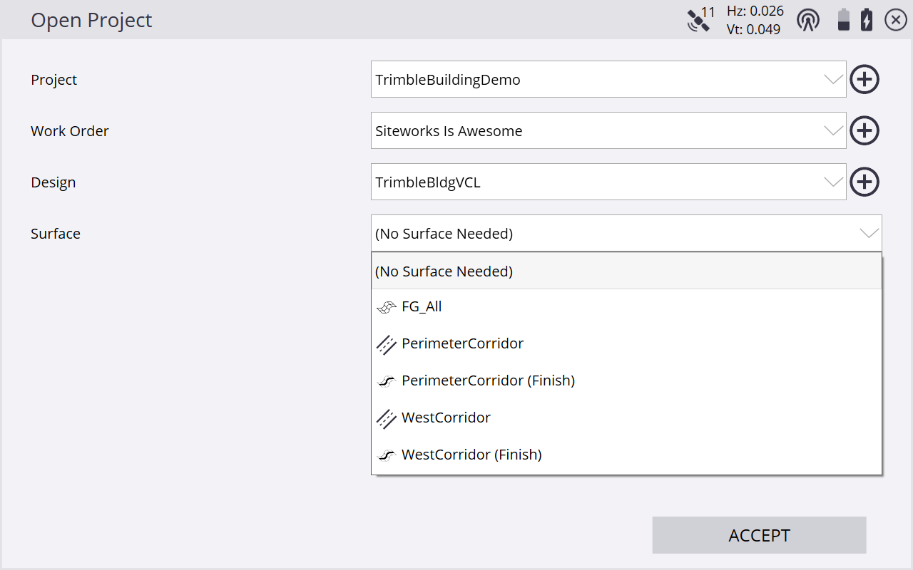
When selecting a VCL design, a Surface option is displayed. This option is used to select the active surface to be used. Only one surface can be the active surface at a time. The option contains all the supported surfaces from the VCL file, and displays an icon to indicate the surface type.
You can change the active surface in the Surface option displayed in the Open Project screen when a VCL design is selected, or from the Surface option in the Surface Settings screen (select Home menu / Settings / Surface Settings). Tip: The Surface option only appears while in the measure feature; if the screen is accessed from the stakeout feature, the option is hidden.