Setting up a pair of SPS Modular receivers to provide heading
The SPS555H receiver is permanently in Heading mode and, when combined with a suitable Trimble receiver, provides GNSS heading. Other SPS Modular receivers can also be paired for heading output if they can operate in Heading mode. See Configuring the receiver pair below.
The SPS555H is a dual-frequency GNSS receiver with a dual-frequency antenna, but it does not operate as a stand-alone DGPS receiver. To compute a true north heading and to be capable of positioning, the receiver requires an output message from another SPS Modular receiver. To determine the precise vector between two moving objects, pair the SPS555H Heading add-on with the SPS855 receiver.
NOTE – The SPS351 GPS receiver does not support the Heading or Moving Base functionality and cannot be paired with another SPS Modular receiver in this way.
Connect the antenna on the SPS555H to the other receiver to determine the precise GNSS heading between the two antennas. The SPS555H receiver shows the heading on the two-line display, and outputs the heading data in NMEA or binary format.
TIP – To create a single, compact GNSS position and heading unit, use the mounting frame provided to stack the SPS555H receiver on top of the other receiver. See below. Use the Marine Heading cable (P/N 57169-10) provided.
The Moving Baseline RTK positioning technique
In most RTK applications, the reference receiver remains stationary at a known location and the rover receiver can move. However, Moving Baseline RTK is an RTK positioning technique in which both reference and rover receivers can move about. Moving Baseline RTK is useful for GNSS applications that require vessel orientation.
The following figure shows vessel heading from Moving Baseline RTK:

|
❶ |
Antenna |
|
❷ |
Vessel heading |
With Moving Baseline RTK, the reference receiver broadcasts Compact Measurement Record (CMR) data, while the rover receiver performs a synchronized baseline solution at 10 Hz. The resultant baseline solution has centimeter-level accuracy. To increase the accuracy of the absolute location of the two antennas, the Moving Reference receiver can use differential corrections from a static source, such as a shore-based reference station.
Mounting a pair of receivers
To obtain a position and heading solution, you need to connect two receivers to make one compact unit. A mounting bracket and interconnecting cable is supplied with the SPS55xH receivers. Set up the receivers, antennas, and cables as shown:

|
❶ |
Dual-frequency rover antenna |
❺ |
SPS55xH |
|
❷ |
Antenna cable (P/N 58957-xx) |
❻ |
SPS Modular receiver |
|
❸ |
Marine heading cable (P/N 67384 or 67384-10) |
❼ |
Mounting bracket (P/N 56830-00) |
|
❹ |
SAE connector |
|
|
Assembling the receivers
The following figure shows a SPS55xH receiver set up to provide a Heading solution. The SPS55xH receiver is on top. To assemble the receivers, you need a Phillips #1 screwdriver and a 1/4" socket set or wrench (spanner).
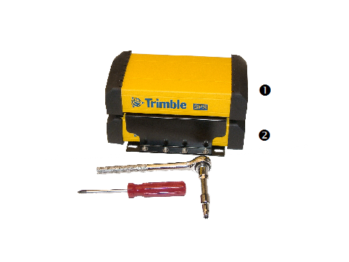
|
❶ |
SPS55xH GPS receiver |
|
❷ |
Other SPSx5x GPS receiver |
To assemble the receivers using the mounting frame that is provided:
-
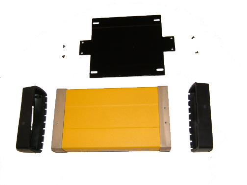
Invert the SPSx5x receiver and then remove the rubber endcaps.
-
Prepare the flat black plate and the four Posi screws. (These are part of the mounting frame.)
-
Position the black plate on the SPSx5x receiver.
-
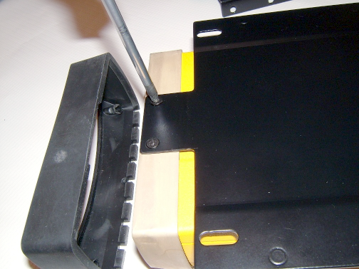
Use the four Posi screws to secure the plate to the receiver. (Secure two screws at each end.) The black plate is now attached to the bottom of the receiver.
-
Replace the rubber endcaps.
-
Invert the receiver again to return it to its normal orientation.
-
Set aside the receiver.
-
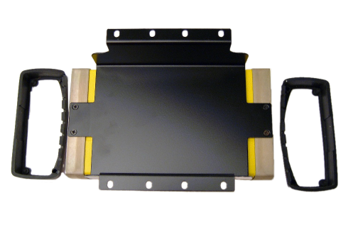
Invert the SPS55xH receiver and then remove the rubber endcaps.
-
Position the black cradle on the SPS55xH receiver. (The black cradle is part of the mounting frame.)
-
Use the four Posi screws to attach the black cradle to the receiver. The black cradle is now attached to the bottom of the SPS55xH.
-
Replace the rubber endcaps.
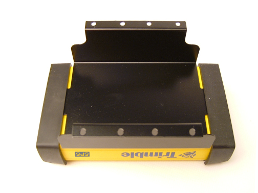
-
Place the black cradle on the black base plate. This places the SPS55xH receiver on top of the SPSx5x receiver.

-
Make sure that the display faces in the same direction on both receivers.
-
Prepare the eight nuts, spring washers, and flat washers.
-
Insert the first bolt. Attach the flat washer, the spring washer, and finally the nut and then tighten firmly. Secure all eight bolts in this way.
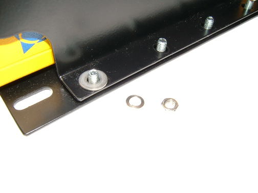
-
Attach one connector from the Marine Heading cable (P/N 67384 or 67384-10) to the 7-pin Lemo on the rear of the SPS55xH receiver. Attach the other connector from the cable to the 7-pin Lemo on the rear of the SPSx5x receiver. The cable can be connected either way around.
The cable connects the two receivers so that the Heading solution is available. The DC or SAE power lead on the cable supplies power to both receivers in the stack.
Installing the receiver
Select a location at which all of the following conditions are met:
-
the receiver is not exposed to temperature extremes
-
the receiver is not exposed to moisture extremes (such as rain, snow, water blasters, or wash systems)
-
the receiver is protected from mechanical damage
-
you can connect and disconnect cables without placing undue stress on them
Mounting the antennas
You must install each antenna at the correct location. Poor or incorrect placement can influence accuracy and reliability.
Ideally, mount the two antennas as far apart as possible and at about the same height on the structure. Mount the antennas fore and aft along the vessel centerline or on a line that is at a known orientation to the centerline. For best results, rotate each antenna so that all antennas in the array point in the same direction. Always mount an antenna at a location that ensures a good view of the sky.
Follow these guidelines to select the antenna location:
-
Choose an area with a clear view of the sky. The antenna must be above any metallic objects.
-
Do not mount the antenna close to stays, electrical cables, metal masts, or other antennas.
-
Do not mount the antenna near a transmitting antenna, a radar array, or near satellite communication equipment.
-
Avoid areas with high vibration, excessive heat, electrical interference, and strong magnetic fields.
Use a 5/8" x 11" stainless steel bolt to mount each of the antennas. There is a threaded bolt hole in the base of the antenna.
WARNING – The GNSS receiver and its cabling should be installed in accordance with all national and local electrical codes, regulations, and practices. The receiver and cabling should be installed where they will not become energized as a result of falling nearby power lines, nor be mounted where they are subjected to over-voltage transients, particularly lightning. Such installations require additional protective means that are detailed in national and local electrical codes.
Configuring the receiver pair
One of the receivers must be nominated as a Heading unit. The other receiver is nominated as a Moving Base unit. For this configuration to work, you must use the Marine Heading cable (P/N 67384 or 67384-10).
To set up the Heading unit:
-
From the Home screen, press
 twice. The Mode screen appears.
 -
Select Heading mode. The receiver display shows two extra settings for heading:
-
Heading Adjustment. Enter a positive value in decimal degrees. The value is applied to the raw heading value before it is output in the NMEA HDT message or displayed on the front panel of the receiver. This value is used when the two antennas are not mounted parallel to the vessel axis.
-
Minimum Heading Solution. Enter the minimum requirement for the GNSS solution that will provide the heading value. The default of RTK Fixed provides the highest precision, but in conditions of extreme multipath or obstruction, an RTK Fixed solution may not be continuously available. In such conditions, select RTK Float if a lower precision is acceptable.
-
To set up the Moving Base unit:
-
From the Home screen, press
 twice. The Mode screen appears.
 -
Select Moving Base mode, and then press
 .
. -
Press
 twice to access the Port screen.
 -
Press
 ,
,  ,
,  to enable MB CMR output on the Lemo port.
Interfacing using the NMEA protocol
The SPS555H receiver can output messages such as NMEA HDT for heading, and NMEA GGA for position. The SPS555H reports the solution status of the moving baseline solution that is being used to compute the heading. However, if the external computer must know the exact quality of the position and its position, you can use the NMEA BPQ from the SPS555H receiver. The base receiver reports the solution status of the position, for example, Fixed Integer, Floating, or DGPS.
Heading output
The heading output from an SPS855 receiver (often this is the SPS55H receiver) in Heading mode is the True North Azimuth from the Heading antenna (this is the unit that receives moving base corrections) to the Moving Base antenna (this is the unit that outputs the moving base corrections). Heading output information is available in the following places:
-
Receiver display
-
Data outputs:
-
GSOF Attitude (see Attitude)
-
NMEA HDT (see HDT)
-
NMEA AVR (see PTNL,AVR)
For more information, see NMEA-0183 messages: Overview and GSOF messages: Overview.
-