Move and Modify CAD Objects Using Grips
You can opt to display grips on the segments of CAD objects (linestrings, polylines, rectangles, polygons, circles, arcs, text, and labels) in the Plan View so you can quickly move and modify the objects just by clicking-and-dragging. Grips can only be displayed on one object at a time; selecting multiple object will hide grips.
To display grips on CAD objects:
- Select Options in the Quick Access Toolbar.
- In the Options dialog, select General > Display and ensure that the Turn on CAD grips box is checked.
- Click OK. Then when you select a polyline, all of the grips are displayed, allowing you to edit any segment by clicking-and-dragging a grip.
To use grips to move and modify CAD objects:
Unless otherwise noted below, when modifying an object using grips, gestures used these keys generally work in these ways:
- Shift - Hold the Shift key while dragging any grip to constrain it to orthogonal (either vertical or horizontal) movement.
- Control - Hold the Control key whild dragging any end point grip to move the entire object. Pressing Control while dragging a midpoint moves the segment in an alignment parallel to itself.
In the Plan View, pick the object you want to move or modify. Then click-and-drag one of the CAD grips as follows:
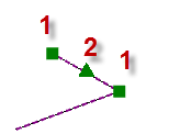
- Polyline:
1. End points - Move the selected segment end point.
2. Midpoint - Move the entire segment. Double-click a midpoint grip to change the segment from a line to an arc, and vice versa. Drag the arc segment's midpoint to change the radius, if needed.
Holding Control while dragging an arc's midpoint snaps the arc to be tangent to the previous segment.
The other attached segments in the polyline move accordingly. If necessary, new segments are created.
Note: CAD grips will not display on a CAD 3D polyline unless you select to edit the polyline (right-click it and select Edit), which converts the polyline into a linestring that includes grips.
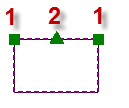
- Rectangle:
1. End points - Move the selected segment end point.
2. Midpoint - Move the entire segment.
The other attached segments in the rectangle move accordingly.
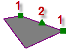
- Polygon:
1. End points - Move the selected segment end point. Press the Ctrl key to move the entire polygon.
2. Midpoint - Move the entire segment.
The other attached segments in the polygon move accordingly.
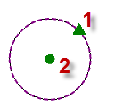
- Circle:
1. Midpoint – Increase or decrease the radius of the circle.
2. Center point – Move the entire circle.
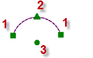
- Arc:
1. End points - Increase or decrease the start or end angle of the arc.
2. Midpoint - Increase or decrease the radius of the arc.
3. Center point - Move the entire arc.
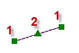
- Linestring
Note: Grips generally work the same way in linestrings, but since segments and vertices can be defined by many different properties, there will be unique constraints. For example, tangency must be maintained in the movement of grips in a three-point arc followed by a tangent arc.
Note: When the next linestring segment is defined by a deflection angle, no grip is shown at the deflection point, because the deflection property must be mainitained.1. End points – Move the selected linestring end point.
2. Midpoint – Move the entire segment, changing the radius (to a valid/tangent limit) in the process.
3. Point of intersection (PI) - Retains the PI arc radius when moved.
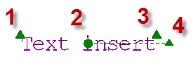
- Text:
1. Text size - Increase or decrease the text size.
2. Insertion point - Move the entire text object.
3. Text string width point - Increase or decrease the width of the text string without changing the text height. Hold Control while dragging the grip to change the width of the text box, causing text to wrap as necessary.
4. End point - Rotate the text object.
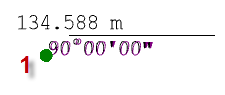
- Labels:
1. Insertion point - Move the entire label.
Using snaps with grips
You can snap grips to other object vertices. You cannot snap to point cloud points; you would need to create a duplicate point at the location of the point cloud point to snap to it.
