Understanding Utility Trenches
Trenches are created to install underground infrastructure or utilities, such as pipelines, gas mains, water mains, or telephone lines, or to access these installations later. In Trimble Business Center, a you can define a cross-sectional trench template that defines:
- the trench shape (bottom, sides, side slopes)
- how the trench ties to existing ground (the target surface)
- the material layers used to backfill the trench
- zones for the depths at which the trench may be constructed
You can define a trench that can accommodate one or more sizes of utility lines/pipes where each pipe can be selected from currently defined shapes in the Material and Site Improvement Manager.
Trench templates
One template can be used for multiple utility runs, especially when used for storm drains. Usually, (with Adjust at nodes enabled) you should not need to make multiple templates for a single type of network. In general, you need a minimum of 1m (36") trench width that includes 0.3m (1') clearance on each side. Trench geometry along the utility line is modeled independently from trench geometry around the nodes. The transition from line to node is controlled by invisible, auto-generated templates dropped before and after the nodes at 1/2 of the node width + the pipe wall thickness and 1/2 of the node width.
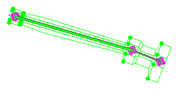
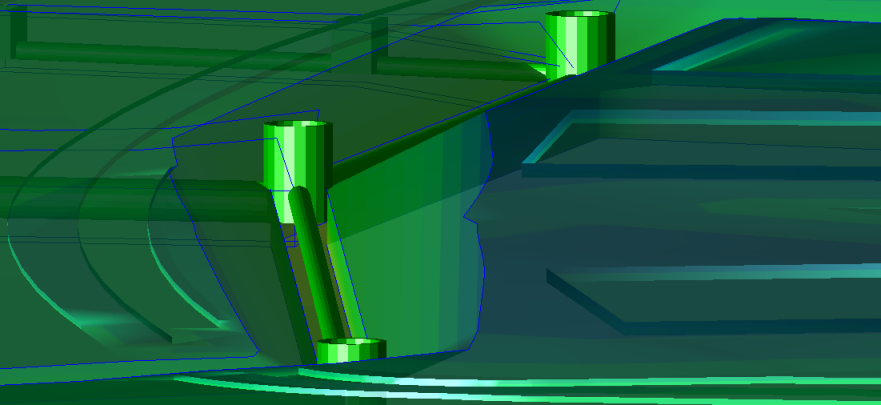
Figure: Automatic trench template widening around nodes
Backfill
Backfilling is the process of putting soil back inside a trench or in a foundation when the excavation has been completed. Backfilling can be used in tasks such as protecting foundations, landscaping, or filling in voids in underground structures.
Backfill material volumes for utility trenches are calculated using the average end area method. Since the tie from the trench to the ground can vary, the volume calculations may vary. Typically, you only need to insert a trench template at the POB of a utility run. Additional templates are automatically added to adjust the trench width and depth at nodes. You can also manually insert a template at a specific location where conditions change, such as under a roadway where you want to use different materials for the backfill.
The best construction practices involve placing the pipe on a firm foundation for maximum performance and structural integrity throughout the design life. It is recommended that unsuitable foundation materials be excavated before installation of the pipe proceeds. If no undesirable foundation material is found, a few inches of bedding should be placed and compacted on the foundation to equalize load distributions along the invert of the pipe. The bedding can be shaped to conform to the outside of the pipe. For a larger pipe, the common practice is to place it on the bedding and carefully tamp or shovel the fill under the haunches to the specified compaction level.
The next layer of backfill, the haunching, is the most important since it is this layer that provides the pipe with support against the soil and traffic loadings. Haunching should be placed in lifts for optimum construction, on both sides of the pipe. Tamp to achieve the specified compaction, or shovel into the area, eliminating voids, if the material does not require compaction. Construction of each lift should be repeated up to the spring line.
Initial backfill extends from the spring line to a minimum above the crown of the pipe. This area of the backfill anchors the pipe and ensures that loads are distributed as evenly as possible into the haunching. When using a material that requires compaction, it is important not to use mechanical compaction equipment directly on the pipe itself.
Final backfill, which extends from the initial backfill layer to the ground surface, does not directly support the pipe. Proper compaction in this area is not nearly so critical for the pipe as in the other layers. However, if roads or drives will be crossing the pipe, a relatively high degree of compaction is needed to prevent pavement settlement. In most installations, excavated materials will be of adequate quality for final backfill.
Depth zones
Use depth zones to set different ranges beneath the target surface at which the utility lines may be constructed. Depth zones are used in the takeoff reporting so that you can charge for the additional effort required to lay a pipe deeper in the ground.
Target surface
The target surface is the existing ground or finished design surface to which the trench template walls tie. Vagaries in the height of this surface above the trench bottom will affect volume calculations.
