Block Insertion Examples
If a block definition includes multiple insertion points, when you insert the block using the Insert Block command pane, the locations you select for the insertion points determines the rotation and scale of the block. Since the Insert Block pane also includes fields that allow you to specify a Z-axis rotation for the block and scaling along its X, Y, and Z axes, any values you enter in these fields will be added to the rotation and scaling changes resulting from the location of the insertion points.
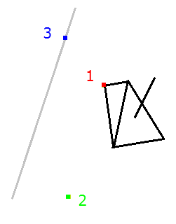
The following example shows a block definition with three insertion points as it was defined in the Create Block command pane.
When the block was inserted using the Insert Block command, the user located insertion points 2 and 3 such that the block was scaled by a factor of 2 along the X axis and 0.5 along the Y axis. In addition, the block was rotated around the Z axis by -15º.
If, in the Insert Block pane, the Scale X, Scale Y, and Scale Z fields each contain a value of 1 and the Rotation field contains a value of 0, no additional changes are made to the scale and rotation of the block.
If the user changes any of the scale values in these fields, the values are multiplied by the scale value derived from the location of the insertion points. In this example, if you changed the Scale X value from 1 to 2, the resulting scaling of the block along the X axis would be 4 (2x2).
If you change the value in the Rotation field, it is added to the rotation value derived from the location of the insertion points. In this example, if you changed the Rotation value from 0º to 10º, the resulting rotation of the block around the Z axis would be 5º (-15º + 10º).
Note: Positive rotation values rotate the block clockwise. Zero is due east.
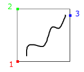
Following are additional examples of block scaling and rotation using insertion points and Insert Block fields. The examples are based on the following block definition, which has 3 insertion points:
![]()
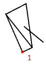
- In this example, only insertion point 1 is used to insert the block in the graphic view. No other changes are made in the Insert Block fields: Scale X = 1, Scale Y = 1, Scale Z = 1, Rotation = 0. As you can see, it looks exactly like the block definition.
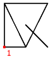
- In this example, only insertion point 1 is used to insert the block in the graphic view. However, the following changes were made in the Insert Block pane: Scale X = 0.5, Scale Y = 1, Scale Z = 1, Rotation = -15º.
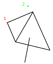
- In this example, insertion points 1and 2 are used to insert the block. Rotation and scaling changes to the block are due to the location of insertion point 2. No other changes were made in the Insert Block pane :Scale X = 1, Scale Y = 1, Scale Z = 1, Rotation = 0.

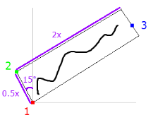
- In this example, insertion points 1 and 2 are used to insert the block. Rotation and scaling changes to the block are due to the location of insertion point 2 along with these changes made in the Insert Block pane: Scale X = 2, Scale Y = 1, Scale Z = 1, Rotation = 15º.
- In this example, all three insertion points are used to insert the block. Rotation and scaling changes to the block are due to the location of insertion points 2 and 3. No other changes were made in the Insert Block pane: Scale X = 1, Scale Y = 1, Scale Z = 1, Rotation = 0
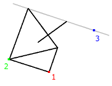
- In this example, all three insertion points are used to insert the block. Rotation and scaling changes to the block are due to the location of insertion points 2 and 3 along with these changes made in the Insert Block pane: Scale X = -1, Scale Y = 0.5, Scale Z = 1, Rotation = -30º.