Create CAD Entities With Vertical Plane Method
The Vertical Plane method can be used to create CAD entities on a vertical plane, a plane defined by selecting two coordinates in the Run View.
To Create CAD Entities With Vertical Plane Method:
- Click on the 3D Coordinate Picker Type pull-down arrow.
- Choose the Vertical Picker from the drop-down list.
- In the Plane View drop-down list, located next to the 3D Coordinate Picker Type field, do one of the following:
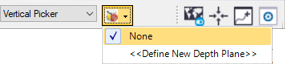
If the depth plane representing the surface on which you want to measure is listed, select it.
If the depth plane is not listed, do the following:
- Select <<Define New Depth Plane>>.
The Define Depth Plane command pane displays.
- Enter a name for the new depth plane
- For Point 1, enter an existing point coordinate or use the pixel picker to select the coordinate on the Run View.
- Repeat for Point 2.
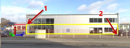
Point 1 and Point 2 must be opposite as illustrated above.
- Select <<Define New Depth Plane>>.
- Click OK.
The new depth plane is represented by a shaded rectangle in the Plan View and in the Run View.
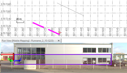
The new depth plane is now available for selection in the Plane drop-down list.
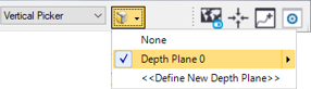
- Use any CAD tool that has a coordinate picker to define a CAD entity on the new depth plane.
