Create Points Using Single Proportioning
The Single Proportioning command enables you to create one or more points that are equally proportioned along a line between two known points. Following are a couple of examples of how the command might be used.
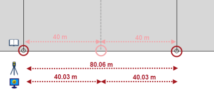
In this first example, a lot marker (pink circle below) could not be located and surveyed in the field. However, lot markers were located and surveyed on either side of the missing marker (dark red circles below), and official records provide the distance from each of the adjacent markers to the missing marker location. In this case, the records specify that that the missing marker is located 40 m from each of the adjacent marker points; however, the measured distance between the adjacent markers is 80.06 m, not 80 m as the records would indicate. To comply with the intent of the recorded distances, which is to place the missing marker half way between the two adjacent markers (proportioned), a new marker point needs to be located 40.03 m from each adjacent marker point, not 40 m.
Although the calculation in this example was relatively easy to apply, the Single Proportioning command handles this type of situation and much more complex ones as well.
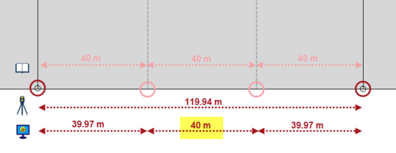
In the next example, two markers indicating a road right-of-way (ROW) are missing (pink circle belows). Lot markers were located and surveyed on either side of the missing markers (dark red circles below). Official records specify that the distance between each of the four markers is exactly 40 m. However, the measured distance between the two known markers is 119.94 m, not 120 m as the records would indicate. To complicate matters, the distance between the two missing markers cannot be proportioned; the ROW must be exactly 40 m wide. Therefore, proportioning can only be performed on the two distances on either side of the ROW. This results in two new marker points that are 39.97 m from their adjacent existing marker points, and 40 m from each other.
The rest of this topic explains how to use the Single Proportioning command to create proportioned points between two selected points or along a line using either planar (grid) or geodetic (global) calculations. As shown in the second example above, it also explains how to mix fixed-length distances (grid or ground) and proportioned distances when creating the new points.
To create points using single proportioning:
- Select Single Proportioning in Survey > COGO.
- Select the appropriate Calculation type:
- Planar (grid) is appropriate for proportioning along a straight or curved line that is 1 km or less.
- Geodetic (global) is appropriate, due to the earth's curvature, for proportioning along a straight line that is greater than 1 km.
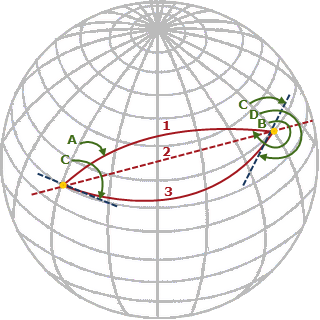
Note: With geodetic calculations, the resulting rhumb line is a spiral; therefore, if its length exceeds 20 km, it cannot be measured accurately using the Inversecommand. To see a comparison of a geodesic path (used by the Inverse command) and a rhumb line (used by the Single Proportioning command),
 click here.
- Do one of the following in the Measured distance fields:
- Select or enter the Starting and Ending points or locations between which you want to create the new proportioned point(s). Right-click in the field for additional selection options.
- Select one or more contiguous line Segments between whose starting and ending points you want to create the new proportioned point(s).
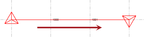
- Select one or more contiguous line Segments and the Starting and Ending points on the line between which you want to create the new proportioned points (as opposed to using the line's starting and ending points). The inherent direction of the line determines the direction for the numbering of any new points. Be sure to select points that are directly on the line (a 1 m snap is built-in to help you make your selection).
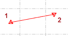
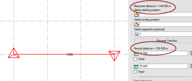
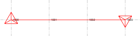
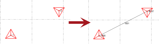
In the graphic views, the starting point is represented by an up-pointing triangle icon (1 below); the ending point is represented by a down-pointing triangle icon (2). Point numbering for the newly created proportioning points starts with the starting point.
The distance between the starting and ending points is displayed as the Measured distance above the Measured distance fields.
- Optionally, click the Reverse Direction button to reverse the starting and ending points.
- Do the following to enter official recorded distances:
- In the displayed Record distance field, enter the official recorded distance from the starting point to the missing point.
- If the distance is intended to be fixed instead of proportioned (for example, a road right-of-way as described in the example above), click the Fixed check box.
- Click the Add button
 or press the Tab key to display a new Record distance field.
 - In the newly displayed Record distance field, enter the official recorded distance from the newly created point to the next point.
- Repeat as necessary to define the distances necessary to create the new point(s).
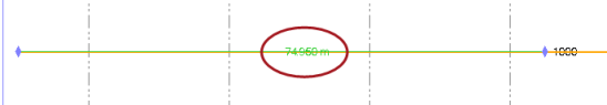
In the following example, the Measured distance is 149.90 m, the first Record distance is 75 m, and the second Record distance is 75 m (neither distance is fixed). Since 149.9 m is less than the Record distance cumulative total of 150 m, the Single Proportioning calculation positioned the new point directly in the middle of line, 74.95 m from each of the adjacent points. In effect, it "split the difference" of -0.10 m for each of the two segments by subtracting 0.05 m from each.
When the first segment is measured:
- If you selected one or more Record distances to be Fixed, select whether to use Gridor Ground distances.
If you selected Planar (grid) for the calculation type in step 2 and you selected the Ground distances option, the Scale factor field is enabled.
- If applicable, click the Calculate button to automatically calculate a combined Scale factor to apply, or manually enter a scale factor.
- Optionally, in Starting point ID field change the default ID displayed.
All new points will be named based on starting with this ID (for example, 1000, 1001, 1002, and so on). Point IDs are applied sequentially, starting from the starting position.
- Optionally, change the Layer on which the new points will be displayed.
- Check any of the check boxes as appropriate:
- Create points at start/end positions - Create two additional points: one on the starting point and one on the ending point. You can delete these points later if you like.
- Create lines - If you are creating new points that are not on an existing line segment, create a line segment from the new points. You can delete this line segment later if you like.
- Create report - Generate a report describing the results of the proportioning. This report is not saved in the project and cannot be re-opened at a later time.
- Create points at start/end positions - Create two additional points: one on the starting point and one on the ending point. You can delete these points later if you like.
- Click the Apply button to create the new point(s) and, optionally, new line.
If you do not obtain satisfactory results, press Ctrl+Z to undo the action. Then make changes as necessary in the Single Proportioning command pane before trying again.