Register a Run
The Register a Run feature provides a way to adjust the trajectory of a run by matching ground control points (GCPs) collected in the field with targets extracted from the acquired scan data. A ground control point (GCP) is an accurately surveyed coordinate location for a physical feature that can be identified on the ground as e.g. a corner on the pavement markings. A target is a point extracted from the acquired scan data.
To register the trajectory of a mobile mapping run:
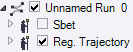
- In the Project Explorer, select a run.
- Select Generate Scans in the context menu to extract the scan data from the selected run.
- Import a ground control points (GCPs) file (in Shape, or ASCII, or CSV format) into the project.
Note: The imported ground control points (GCPs) are displayed in the Plan View and in the Project Explorer, under the Points node.
- Select Register a Run in Mobile Mapping > Processing to display the Register a Run command pane.
Note: The Register a Run command is dimmed when you select a run which does not have at least a single scan generated.
- Use the default name (RunName Trajectory) or input a name in the Registration Name field. This name will be given to the computed trajectory.
- Click on the Registration Type pull-down arrow and choose a registration method:
- Global: This method does not apply a local adjustment on the trajectory near the ground control objects, but a global shift on the trajectory as a whole without rotation. This method has to be used in situations in which there are consistent differences between the laser data and the ground control points. A situation in which the data can be corrected with a simple shift.
- Local: This method does apply a local adjustment on the trajectory with interpolation between ground control points. This method is suitable for a local adjustment of a run, not for systematic error along the run and for adjusting outside the ground control points set.
- Global, and then Local: This method does apply first the Global method and then the Local method.
- In the Project Explorer, under the Points node, select a ground control point (GCP).
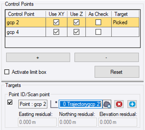
- In the Register a Run dialog, click the Add Selection to Control Points button to put the selected ground control point (GCP) in the Control Points list.
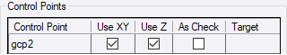
For the selected ground control point (GCP), choose to optimize only the XY coordinates (Use XY), or only the Z coordinate (Use Z), or both by checking the corresponding check box(es).
Note: A validation point (VP) (As Check) is a ground control point (GCP) that is used for only measuring the quality for the registration. In the same manner as a normal ground control point (GCP), you need to pair a validation point (VP) with a picked target. The resulting XYZ residual values will not be taken into account in the registration, that's why all the selected ground control points (GCPs) cannot be set as validation points (VPs). If you set all the selected ground control points (GCPs) as validation points (VPs), an error will pop-up and will prompt you to have at least one ground control point (GCP) for the calculation.
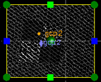
- If necessary, check the Activate Limit Box option. A limit box is a flat box (in the Plan View) or a 3D box (in the 3D View) used to hide all objects outside the box and to only focus on the target to pick. Resize the limit box to remove potential parasite points over the target.
- If necessary, use the Activate Target-Bundle Adjustment option.
- When the option is checked, the bundle adjustment of targets will be performed at acquisition intervals of 250 meters. This setting is suitable when there are few GCPS, and the accuracy of the GCPs is moderate and the precision in target picking is less stringent.
- When the option is unchecked, the bundle adjustment of targets will be performed at acquisition intervals of 70 meters. This setting is ideal when there are more GCPs available, and the accuracy of the GCPs is high and the precise target picking is necessary.
- In the Control Points list, select a ground control point (GCP). The selected ground control point displays in the Targets panel, and centers in the Plan View window. At the same time, the Point Cloud Smart Picking window opens.
You need to pick in the scan the center of the target which should match the selected ground control point (GCP). This point is called Picked Target. The Point Cloud Smart Picking tool lets you select the Type of Point Picker to use (Default, Intersected Plane and Road Mark). After picking roughly a scan point, the software automatically computes the best point and displays that point in editable views.
- Default - This picking type has to be used to pick a target close enough to the ground control point (GCP) by snapping a point of the point cloud. You will not use this option to create a roadmark, or intersected plane-based point.
- Intersected Plane - This type of picking has to be used if your dataset contains e.g. black and white checkerboard targets.
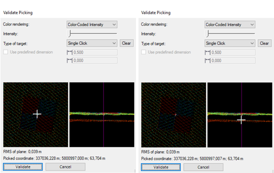
Start by picking roughly a point in a point cloud. The software automatically fits a plane in the neighborhood of the picked point, and projects the picked point onto it. The Picking Preview window opens letting you select the Type of Target to use. It displays:
- An overhead view of the projected point, as well as its 3D coordinates and the RMS value of the fitted plane.
- A side view of the projected point, perpendicular to the trajectory.Select Single Pick as Target Type and pick a different location in the overhead view to fine-tune the location of the projected point. You do not have to pick a displayed point. Once satisfied with the XY coordinate values of the target, update the Z value until the projected point fits the point cloud by picking in the side view.
Select Checkerboard as Target Type to draw an overlay pattern over a checkerboard target:
- Left Click - Use dimension constraints to pick an overlay pattern of 0.5 meters of middle line, or freely pick target pattern dimensions.
- Right Click - If required, pan the defined pattern to position it exactly over the checkerboard target.
- If required, click Clear to cancel the defined pattern and define a new one.
- Once satisfied with the XY coordinate values of the target, update the Z value until the target fits the point cloud by picking in the side view.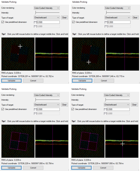
Select Diamond as Target Type to draw an overlay pattern over a diamond target:
- Left Click - Use dimension constraints to pick an overlay pattern of 0.4 meters of the edge length, or freely pick target pattern dimensions.
- Right Click - If required, pan the defined pattern to position it exactly over the diamond target.
- If required, click Clear to cancel the defined pattern and define a new one.
- Once satisfied with the XY coordinate values of the target, update the Z value until the target fits the point cloud by picking in the side view.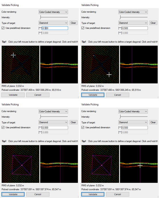
Select Rectangular as Target Type to draw an overlay pattern over a rectangular target:
- Left Click - Use dimension constraints to define an overlay pattern by picking three connected vertices, or freely pick target pattern dimensions.
- Right Click - If required, pan the defined pattern to position it exactly over the rectangular target.
- If required, click Clear to cancel the defined pattern and define a new one.
- Once satisfied with the XY coordinate values of the target, update the Z value until the target fits the point cloud by picking in the side view.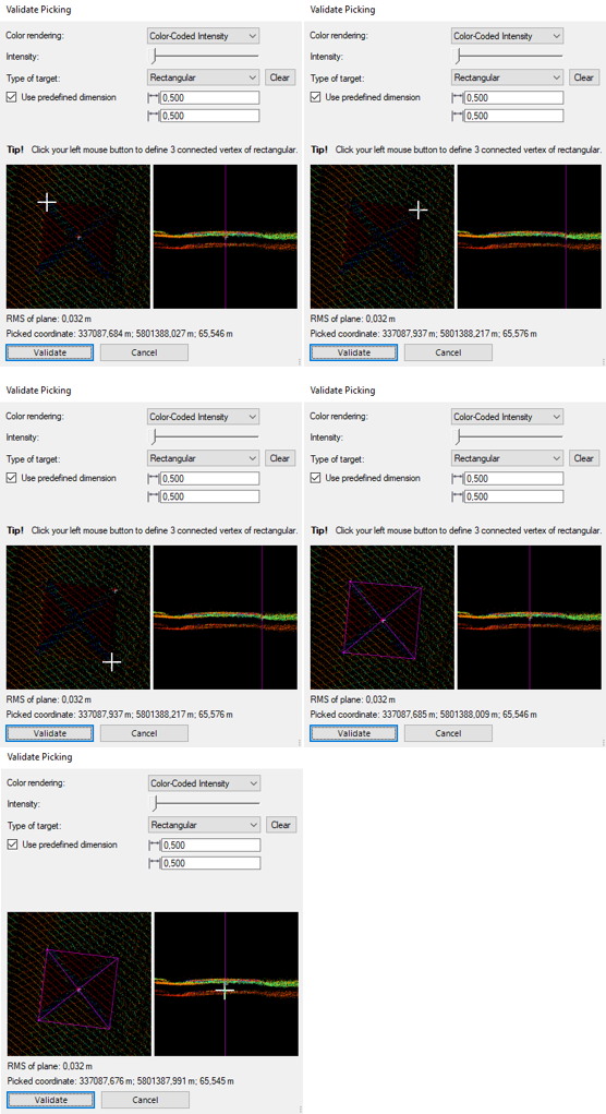
Select GV Target as Target Type to draw an overlay pattern over an L-shape target:
- Left Click - Use dimension constraints to pick an overlay pattern of 0.08 meters for the Bolt. Optionally, change the size of the Bolt or its orientation by clicking Invert.
- Right Click - If required, pan the defined pattern to position it exactly over the L-shape target.
- If required, click Clear to cancel the defined pattern and define a new one.
- Once satisfied with the XY coordinate values of the target, update the Z value until the target fits the point cloud by picking in the side view.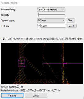
When you are ready, click the Validate button, or press the Enter key. - Road Mark - This picking type has to be used if your dataset contains pavement markings. Select this type to pick a point on a roadmark edge line in a point cloud.
Start by picking a point in a point cloud roughly near the roadmark edge line for which you want to create a point. The Picking Preview window displays and shows an overhead view of the roadmark edge line and the automatically selected pick location, and its 3D coordinates.
If necessary, pick a different location in the Picking Preview window to fine-tune the location of the point on the roadmark edge line. You do not have to pick a displayed point. When you are ready, click the Validate button, or press the Enter key.Notes:
- For the Road Mark and Intersected Plane picking modes, you can change the point cloud rendering setting. Gray-Scale Intensity renders the point cloud using a gray scale based on the intensity of each point. Color-Coded Intensity renders the point cloud using a color scale based on the intensity of each point. Color By Distance to Plane renders the point cloud using a color scale based on the elevation information of each point.
- For the Intersected Plane picking mode, you can use the Intensity slider to decrease (or increase) the contrast of a target to pick, especially when the target has some reflective parts.
- Once you have validated the picked target:
Note: If the Registration Auto-Saving option in Options has been set to "on," the picked targets will be automatically saved in the project in a specific file (Targets.csv) even if the project has not been saved, or if the Registration Run command has been closed without applying. The next time you reopen the command, you will be prompted to reload the picked targets. If you choose “No”, they will be emptied from the targets.db file and you will not be able to retrieve them.
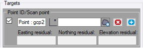
- The 3D coordinates of the picked target display in the Target field. The Easting, Northing, and Elevation residuals, which indicate the distance differences between the chosen Ground Control Point (GCP) and the target, are displayed with their corresponding directional signs.
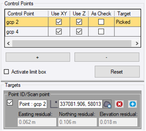
- In the Plan View, the picked target has the name of the ground control point (GCP) and the representation shown below:
- A pair of a ground control point (GCP) and a picked target is enough to perform the registration. If you wish to use more, do one of the following:
- Select a new ground control point (GCP) from the Control Points list in the Registration Run dialog.
- Or click to add a new pair pairing line and choose a new ground control point (GCP) from the Control Points list.
 - If there are more than one pair of ground control points (GCPs) and picked targets in the Targets pane, you can choose a pair to be used in the registration by keeping the pair checked and unchecking the rest.
- When you pick a point, the following warning may appear:
 means that the picked point is not a 3D point (no Z coordinate) and/or does not belong to the scan of the run to register.
 means that the picked point does not belong to the most recent scan of the run to register.
In both cases, pick again a new target.Note: The distance in a pair of points cannot exceed the allowed maximum distance of 30 meters (or 100 feet).
- The 3D coordinates of the picked target display in the Target field. The Easting, Northing, and Elevation residuals, which indicate the distance differences between the chosen Ground Control Point (GCP) and the target, are displayed with their corresponding directional signs.
- If necessary, you can open the Point Cloud Smart Picking window again and change the picked target location by clicking
 .
. - Click Compute. The computation consists of reducing the absolute error between the ground control points (GCPs) and the corresponding targets. The result is an adjusted trajectory displayed in blue and a set of updated targets.
The picked target is renamed to RunName TrajectoryGCPName and the updated target has the following name: RunName TrajectoryGCPName*.
You can visualize the new targets as well as the initial trajectory (in green) and compare it with the computed trajectory (in blue).
Note: The Reset button restores all point pairs to the original saved value. There is no restoration when you register the trajectory of a run but only when you edit it.
- If necessary, repeat step 10 to add additional pairs of points on top of the previous pair(s).
Notes:
- TBC renames incrementally picked targets and updated targets that are involved in multiple registration cycles to avoid having duplicated names.
- TBC will prompt you to discard collected points if you close the Register a Run tool without applying. - Click Apply. The blue trajectory is created in the TBC database, and appears nested beneath the selected run node in the Project Explorer, as an adjusted trajectory (named following the run name with the suffix Trajectory).
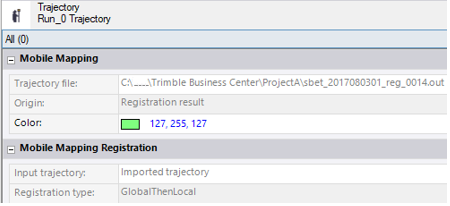
For each adjusted trajectory, a SBET (or NAV) file with the "reg" flag (1) and an order (2) is created and rooted under the project folder.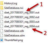
Note: In case of a single head configuration (one high-end laser scanner acquisition), it does not matter which scan is used (left or right) for the registration.
