Work with Feature Symbols
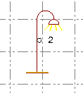
A representative symbol can be assigned to a point feature that displays in graphic views.
Following is an example of a feature symbol displayed in the Plan View.
Note: When you import a Feature Definition (.fxl) file into TBC, all of the symbols defined in the file are imported as well, regardless of whether or not they are assigned to any feature definitions.
To assign a symbol to a point feature definition:
- In the Project Explorer, right-click the node representing the point feature definition to which you want to assign a symbol.
- In the context menu, select New Symbol.
A new Symbol node displays nested beneath the selected Point Feature Definition node in the Project Explorer. In addition, the Symbol Definition Properties pane displays.
- Complete the fields as described in "Properties" below.
Your changes are saved automatically.
To edit or delete a symbol:
In the Project Explorer, right-click the node for the symbol you want to edit or delete and do either of the following:
- Select Properties to display the Polygon Feature Definition Properties pane. Then make any necessary edits as described in "Properties" below. Your changes are saved automatically.
- Select Delete.
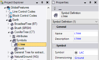
Properties:
|
General |
|
| Name |
Enter a name for the symbol. |
| Description |
Optionally, enter a brief description of the symbol. (The description is not used during fieldwork.) |
|
Symbol |
|
| Symbol |
Select a predefined symbol to represent the feature. If you need to import a symbol, select the <<Import symbols>> option. The Symbol Manager dialog displays, allowing you to import and delete symbols. For instructions, see Importing and Removing Symbols. |
| Dimensioning |
|
|
Style |
|
| Color |
Select the color for the symbol. Or, optionally:
Note: The symbol you selected in the Symbols list may have a predefined color scheme that cannot be changed. In this case, you cannot select a color in the Color list. |
|
Rotation |
|
| Associated attribute |
Optionally, select an attribute assigned to the feature definition on which the rotation value is based. |
| Rotation |
If <None> is selected in the Associated attribute drop-down list, enter a rotation value for the symbol. |
|
Scale |
|
| Associated attribute |
Optionally, select an attribute assigned to the feature definition on which the scale value is based. |
| Scale |
If <None> is selected in the Associated attribute drop-down list, enter a scale value for the symbol. |
|
List Attribute |
|
| Associated attribute |
If the feature includes one or more |
| Attribute value |
When a List attribute is selected in the Associated attribute drop-down list, select the symbol that will display after feature processing. |
 list feature attributes