Work with Offset Feature Lines
If you want to create one or more offset lines for a line feature, as opposed to a single centerline, you can assign offset lines to the feature definition used to define the line. For example, you might want to add two offset lines to the line feature for a sidewalk: one that is 2 units to the left of the sidewalk centerline to define the left edge and one that is 2 units to the right of the sidewalk centerline to define the right edge. In this case, you could add two offset lines to the feature definition: one using a horizontal offset value of 2, and one using a horizontal offset value of -2. You could even use different colors and styles for the offset lines if you wanted.
Note: When you add an offset line to a line feature definition, the centerline is no longer displayed.
To assign an offset line to a line feature definition:
- In the Project Explorer, right-click the node representing the line feature definition to which you want to assign an offset line.
- In the context menu, select New Line.
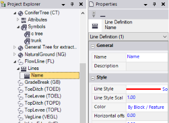
A new Lines node displays nested beneath the selected Line Feature Definition node in the Project Explorer. In addition, the Line Definition Properties pane displays.
- Complete the fields as described in "Properties" below.
Your changes are saved automatically.
To edit or delete an offset line:
In the Project Explorer, right-click the node for the offset line you want to edit or delete and do either of the following:
- Select Properties to display the Line Definition Properties pane. Then make any necessary edits as described in "Properties" below. Your changes are saved automatically.
- Select Delete.
Properties:
|
Options |
|
| Name |
Enter a name for the offset feature line. |
| Description |
Optionally, enter a brief description of the offset feature line. (The description is not used during fieldwork.) |
|
Style |
|
| Line style |
Select the line style to use for the offset line. Optionally:
|
| Line style scale |
Enter the scale factor to apply to the line feature. The higher the number, the larger the scale. If, for example, you have a dashed line with 12 dashes and you change the line style scale from 1 to 2, the line will then have 6 dashes. |
| Color |
Select the color for the line. Optionally:
|
| Horizontal offset |
Type the distance to horizontally offset the line from the feature center line. |
| Vertical offset |
Type the distance to vertically offset the line from the feature center line. |
| Offset unit |
Ground - Select this option if you expect to use the project's distance measurement units. Paper - Select this option if you expect to print or plot data in the project. |
