Calibrate Mobile Mapping Laser Scanners
A system calibration describes the estimation of the exact translation and orientation of each sensor referring to an internal virtual reference point of the sensor head. For a Trimble MX series mobile mapping system, each sensor has its individual set of:
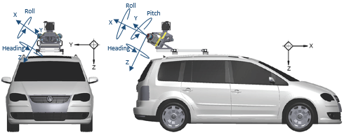
- Lever arms (offsets in translation – X, Y and Z):
X-axis in the driving direction to the front.
Y-axis in the driving direction to the right.
Z-axis in the down direction. - Boresight angles (offsets in orientation around the X, Y, and Z-axes, respectively Roll, Pitch and Heading).
In a calibration process, the offsets in translation are known for all sensors and do not need to be estimated while the offsets in rotation need to be. In TBC, up to the 5.21 version, laser scanners are calibrated out of the application and the calibration values are imported into TBC from a JSON format file. The Calibrate Laser Scanners feature allows you to calibrate the laser scanners of the MX series mobile mapping systems in TBC.
Prerequisites:
- Create a VCE project and if necessary, change the coordinate system so that it matches the coordinate system for the mobile mapping data to import.
- Import the mobile mapping data (*.mxdb) which should have the following requirements:
- Four runs, two in a direction (forward and backward), and two orthogonal (forward and backward as well).
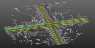
- The four runs should form a proper crossing (angle between orthogonal runs should be the closest to 90°, with a precision of more or less 30 degrees), with:
- Enough overlap.
- Facades present in each direction, and in a sufficient quantity.
- A few or no vegetation ideally.
- 20-meters distance long: Runs should be at least 20 meters long from each side of the crossing. To ensure an efficient calibration, runs should be ideally 80 meters long, 40 meters from each side of the crossing.
- Four runs, two in a direction (forward and backward), and two orthogonal (forward and backward as well).
To calibrate mobile mapping laser scanners:
- In the Project Explorer, select a laser scanner from the Capture Devices node.
- From the pop-up menu, select Calibrate Laser Scanners. The Calibrate Laser Scanners dialog opens.
- In the Project Explorer, select four runs (Run_0, Run_1, Run_2 and Run_3) of the same crossroad.
- If required, select Toggle Active Trajectory to visualize which run intersects with others.
Note: An error message will pop up if less than four runs are selected.
The Calibrate Laser Scanners dialog displays for each laser scanner the calibration values (Heading, Pitch and Roll) before calibration.
- If required, check the Open Cutting Plane View option.
- Press Compute. The calibration starts and may take a while.
Once finalized, the Plan View displays the generated scan data for the four runs and the Calibrate Laser Scanners dialog displays:
- The computed calibration values of each laser scanner.
- The Overall Overlap value which refers to the percentage of points used in comparison to the total of points generated. The Overall RMS value, which refers to as the average of RMS values between used scans.
- For each set of two parallel runs, a set of two Timestamps and three RMS values. Only the generated sub-scans around the crossing are considered. Each set represents a section of 20 meters between two parallel runs, and the two Timestamps the center of this section with regard to each run.For each Timestamp, RMS values are computed along three directions (Tangential, Orthogonal and Vertical) as illustrated below:
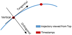
The RMS values give an indication of how much parallel runs are close after the calibration process, in each direction:
- Good RMS values do not mean that the calibration succeeded. A visual check is needed. On the other side, bad RMS values mean that the calibration failed, which can be confirmed with a visual check.
- If the Cutting Plane View option has been checked, the Cutting Plane View tab opens directly beneath the Plan View tab. If it is not already displayed, display the 3D View. A plane whose name is Mobile Mapping Cutting Plane is created: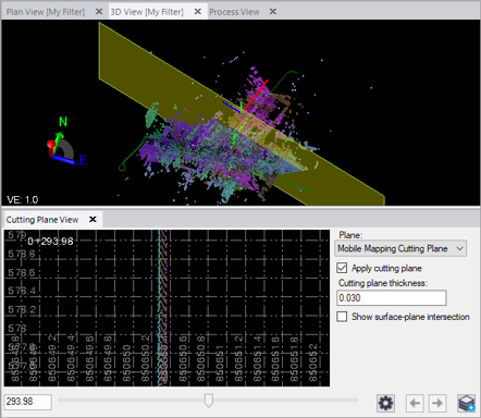
- In the Project Explorer pane, it is represented as a plane node nested beneath the parent Plane node.
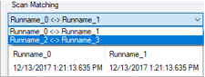
- In the 3D View, it is represented as a yellow cutting plane at the beginning of the first set of runs (Run_0 <-> Run_1).
- Points intersecting the cutting plane display in the Cutting Plane View tab, providing a profile view based on the cutting plane's orientation and position.
- Optionally:
- Change the cutting plane thickness value. This value determines which points are displayed in the Cutting Plane View.
- Change the rendering option to Scan Color to display the scan data with one color per scan.
- Increase the display size of the scan data points by selecting Point Size.
- Use the slider control located at the bottom of the tab to move the cutting plane to any position along the set of runs to better visualize the gap between the scan data of the two runs.In the Calibrate Laser Scanners dialog, choose Run_2 <-> Run 3, and perform a visual check if needed as previously described.
- Press Apply.
