Register Multiple Pairs of Runs
The Register Run to Run feature provides a way to register a set of runs, two by two in batch mode, from the same mission or from different missions. In a pair of runs, one has to be defined as a Reference Run meaning that its trajectory will not change and the other as a Run to Adjust, its trajectory will be optimized with regards to the Reference Run's trajectory. As a result, a new trajectory will be created and the scan data of the Run to Adjust will be updated with this new trajectory so that the scan data of both runs will match well together.
Prerequisites:
In a pair, the two runs need to have:
- At least one scan, whatever the scan (left or right).
- Enough overlapping scan data along the trajectories.
To register multiple pairs of runs:
- Import several missions into your TBC VCE project.
- Select Register Run to Run in Mobile Mapping > Processing to display the Register Run to Run command pane.
- Input a name in the Registration Name field. This name will be given to all computed trajectories.
- Select a pair of runs, one as Run to Adjust and the other as Reference Run:
From the same mission: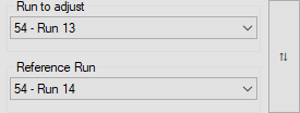
Or from two different missions: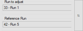
Here, "33", "42" and "54" are the non-zero digits of a mission ID.
- Optionally, click Swap Runs to invert the two selected runs.
- Click + to add the pair in the batch-processing.
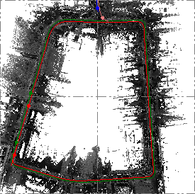
- In the Plan View, the Run to Adjust and the Reference Run are displayed respectively in green and red.
In the Register Run to Run command pane:
- The selected run is removed from the Run to Adjust list.
- “Missing TMX Files for “Runname_X and Runname_X+1” in the Status column means that no scan data has been generated.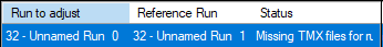
Note: "Missing TMX files" does not prevent you from launching the Register Run to Run directly, and you do not need to generate the scans first, TMX files will be generated on the fly.
- “Blank” in the Status column means that scan data has been generated.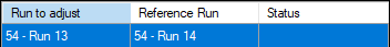
- Repeat the steps from 4 to 6 to add another pair.
- Optionally, do one of the following:
- Select a pair and click - to remove it from the batch-processing list.
- Select a pair and click or
or  to change the processing order.
 - For the Update Scans option, do the following:
- Uncheck to not generate the scan data after the registration.
- Check to generate the scan data after the registration for the Run to Adjust, based on the adjusted trajectory and to enable the Open Cutting Plane View option. - To inspect the registration results visually, check the Open Cutting Plane View option.
- Click Compute.
- TBC registers the first pair. Once done, a new trajectory is created in the TBC database. It appears nested beneath the Run to Adjust node in the Project Explorer, as an adjusted trajectory (named as follows: GivenName: Runname_X To Runname_X+1).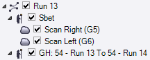
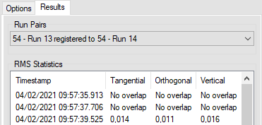
- TBC also computes some statistics and displays them in the Results tab. Timestamps are computed every twenty meters depending on the speed of the vehicle. For each Timestamp, three RMS values are computed along three directions (Tangential, Orthogonal and Vertical) as illustrated below.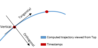
- If the Update Scans option has been checked, new Scan nodes are created and nested beneath the created trajectory below the Run to Adjust in the Project Explorer pane.
- Created scans are displayed in the Plan View: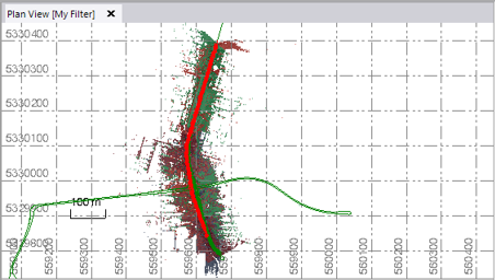
- Once done for the first pair, TBC registers the remaining pairs following the given order.
- Click Compute.
- To check the registration results as statistics, select a pair from the Results tab.
- TBC creates a plane named MissionID Last Two Digits - Run to Adjust for each pair, and displays the plane of the first pair in the Cutting Plane View.
Note: The Cutting Plane View tab should open beneath the Plan View tab. If not, display it by clicking Cutting Plane View in Point Clouds > View.
This plane appears as:
- A plane node nested beneath the parent Plane node, in the Project Explorer pane.
- A yellow cutting plane at the beginning of the Run to Adjust.
- Points intersecting the plane provide a profile view based on the cutting plane's orientation and position.
- Optionally, change the Cutting plane thickness value. For example, a wider thickness will typically result in additional points being displayed in the view.
- Optionally, keep the Scan nodes of the pair checked and uncheck the rest in the Project Explorer.
- Change the rendering option to Scan Color to display the scan data with one color per scan.
- Increase the point size of the scan data by selecting Point Size.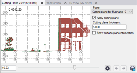
- If applicable, optionally check the Show surface-plane intersection check box to display a visual indicator of where the cutting plane intersects with a surface.
- Use the slider control located at the bottom of the tab to move the plane to a position along the Run to Adjust to better visualize the gap between the scan data of the two runs.
- To help you visualize the plane along the trajectory, display the 3D View.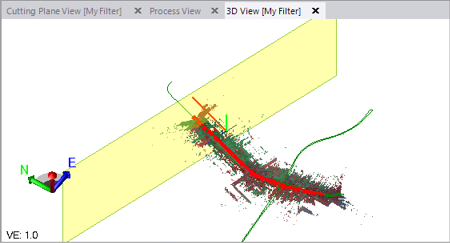
- Repeat the steps described in step 13 for another plane.
