Process Raw Trajectory Data
The feature enables you to compute a Smoothed Best Estimate of Trajectory (SBET) within TBC using the raw inertial, GNSS satellites, and base station data, without having to use the Applanix's POSPac MMS application and to import the trajectory into TBC.
Note: The requirement to run the feature is to have the Applanix's POSPac MMS application (from version 8.6 and a valid license) installed alongside TBC.
To process the raw trajectory data:
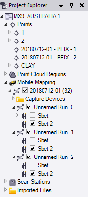
- In the Project Explorer, right-click the Mission node and select Process Raw Trajectory Data in the context menu. TBC automatically loads the raw Pos data.
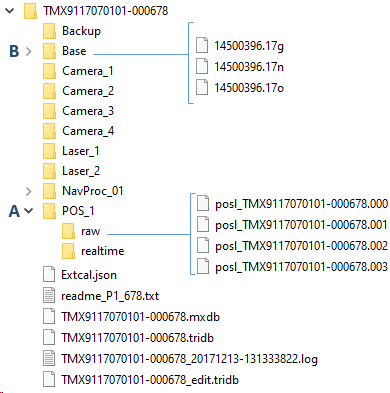
- A - Raw POS Data (includes raw Inertial Measurement Unit [IMU] data and raw GNSS data) - It is a list of POS logged files. They can be found in the POS_1 / Raw folder which is automatically selected. TBC will sequentially process the entire series of valid POS logged data files starting from the first file selected.
- B - Raw Base Station data - A Base Station is a GNSS ground station generally placed on a known point.
Drag and drop or import the Base Station data into TBC. The data can be found in the BASE folder in the RINEX format (.yyo). YY is two-digit year. The demo data set shows 17o which is an observation file for the year 2017.
17g and 17n are ephemeris files. Do not import the ephemeris files into TBC.
Note: Import the Base Station data into TBC before running the Process Raw Trajectory Data command.
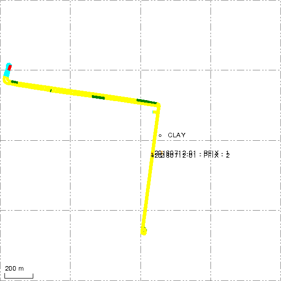
The Base Station, once imported, is displayed in:
- In the Plan View: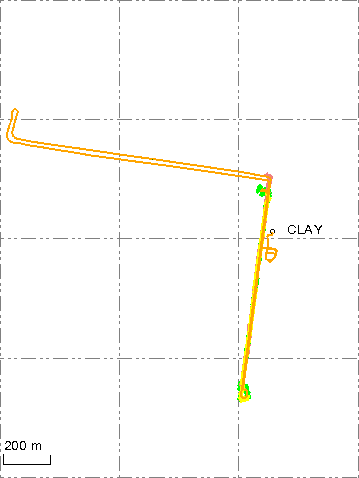
- In the Process Raw Trajectory Data dialog: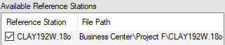
- And is copied under the project folder. - SBET Output Folder: TBC will automatically create the NAVPROC folder under the project folder, and will put the SBET trajectory file under the folder once it is computed.
- Backup SBET Next to MXDB: TBC will copy the SBET trajectory file (which will be created) and create a log file (with the frame and epoch information used to create the SBET trajectory file) and put both files in the raw data folder next to the mission database file (.mxdb).
- Apply PFIX: TBC will display the Custom Events file found in the PFIX folder under the Trimble Business Center project folder, if there is one. The option is grayed-out by default. It will be enabled only if the selected SBET output folder exists and the Trimble Business Center project contains a computed POSPac project.
- Define the Processing Settings: TBC automatically fills the below fields with the information found in the POS logged files, like GNSS/Inertial/DMI Sensors Lever Arms and GAMS Baselines settings which are set in the vehicle before the data collection. Double check the settings values and if needed modify them.
- Computation Mode: Select the GNSSS-Inertial processing mode to compute the Smoothed Best Estimate of Trajectory (SBET) between IN-Fusion+ Single Base and IN-Fusion+ PP-RTX.
IN-Fusion+ Single Base provides high-accuracy GNSS positioning using corrections from a nearby local base station.
IN-Fusion+ PP RTX delivers high-accuracy GNSS positioning globally using Trimble’s satellite or internet-based RTX corrections, without the need for a local base station.
- Time Start & Time End: Define the start time and end time for the GNSS-Inertial processor, based on the Base Station in your project area. The time format is GPS seconds of the start week.
- GAMS (GNSS Azimuth Measurement System) is an additional GNSS antenna used in the field to speed up the initialization of the navigation system in the MX system, by estimating the orientation of the vehicle such more quickly compared to when using a single-antenna solution.
DMI (Distance Measuring Indicator) is an additional sensor mounted on the vehicle to improve the measurement accuracy of the MX system.
Lever Arm refers to the displacement between two body coordinate frames, measured from the origin of one frame to the origin of the other, expressed as a three-dimensional vector, indicating the position difference between the two coordinate frames in terms of three spatial dimensions.
Lever Arm measurements for DMI or GAMS are performed in the so-called vehicle frame from the external reference point to the center of the tread where the DMI-equipped wheel makes contact with the road or to the Antenna Phase Center of the GAMS Antenna (secondary GNSS Antenna) as measurement of distance (in meters) along three different axes. The orientation of the axis in the vehicle frame is defined as follows:
- Positive X-axis = In forward driving direction
- Positive Y-axis = Right side of the vehicle
- Positive Z-axis = Downward
GAMS Standard Deviation refers to the assumed accuracy of the entered lever arm.Note: The GAMS checkbox and the GAMS standard deviation field are dimmed if the GAMS sensor has been disabled during the mission acquisition.
DMI Lever Arm Standard Deviation refers to the assumed entered lever arm.
DMI Scale Factor is expressed in Pulses per Meter (PPM) and represents the inverse of the scale factor used to convert the DMI pulse count to the distance traveled. The sign of the scale factor (positive or negative), depends on the DMIs installation side.
- DMI installed on the left side of the vehicle: scale factor is positive
- DMI installed on the right side of the vehicle: scale factor is negative
Note: To find the exact scale factor value for the measured wheel diameter of the vehicle in the Trimble MX Distance Measuring Indicator Installation & Operation Manual, in the DMI Scale Factor section.
DMI Scale Factor Standard Deviation specifies the assumed accuracy of the entered scale as a percentage. The default value is 5%. Increase the setting if the scale factor is not known with 5% accuracy, and set it to 100% if It is not known at all.Note: The DMI checkbox and all the related fields are dimmed if the DMI sensor has been disabled during the mission acquisition.
- Initialization Mode: Choose a Initialization mode:
VNAV: The real-time VNAV attitude solution can be used to provide an initial heading so that mode transition from Coarse Leveling to Fine Alignment can occur. The NAV heading solution is used once to effect the mode transition.
Gyro-compassing: This is the default setting and is used if the IMU is sufficiently accurate to create a gyro-compassed heading or if none of the other initialization methods are available, the nominal gyro bias property is used to predict gyro-compassed heading at the current latitude.
GAMS: The GPS compass can provide initial IMU heading when secondary GNSS observables are available and the GAMS option is ON.
GAMS and Gyro-Compassing will use a combination of GAMS and IMU data. - Antenna Manufacturer & Antenna Type: The information is retrieved automatically from the RINEX file while the Base Station file is being imported (the rover antenna model should be Tallysman/33-3970 GNSS for an MX9 (or MX50) system and Trimble 112735 GNSS for a MX90 (or MX60) system.
- Multipath is an estimate of the level of the obstruction and echo of the GNSS signals. There are three options to select: Low for a good GNSS coverage and Medium / High for a degraded GNSS coverage, such as in urban canyon, narrow streets, dense foliage environments. Medium is the default Multipath setting.
- LiDAR QC (Refne with scans): Check the LiDAR QC (Refine with scans) check box to enable the LiSDAR QC tab.
Note: If the MATLAB Runtime version R2024b (24.2) is not installed, a message will prompt you to install it. - Generate QC Report: To view the plots resulting from the processing, check the option.
- Computation Mode: Select the GNSSS-Inertial processing mode to compute the Smoothed Best Estimate of Trajectory (SBET) between IN-Fusion+ Single Base and IN-Fusion+ PP-RTX.
- Click Compute. If the datum and epoch used in the project are:
Known by POSPac, a SBET trajectory file will be created in the datum and epoch of the project, with the following name: sbet_[mission name].out
Unknown by POSPac, a SBET trajectory file will be created, first in ITRF00 and then in the datum and epoch of the project, with the following name: sbet_[mission name]_[frame].out
The created SBET trajectory file will be colored according to the values of the computed RMS.
The created SBET trajectory file and the report can be found respectively under the Export and Report folders under the NAVPROC folder.