Drape Objects on a Point Cloud
Use the Drape Objects on Point Cloud command to vertically change the elevation of a CAD point and/or each of the vertices defining a CAD line, alignment, or trajectory to a point or group of points in a point cloud. Optionally, apply a specified horizontal offset to CAD linear objects during the elevation process. Or, select to automatically create points for CAD linear objects when the interval between nodes on the polyline exceeds a specified distance. The command provides a variety of options for searching for the appropriate point cloud point to which to change the elevation, each of which is based on a specified search radius and the projection of the vertex through the point cloud along a Z axis.
Note: Vertical lines are not supported with this command.
Prerequisites:
- See the Subscription Plans page. For a license matrix by command, see the License page in the TBC Community. Also see View and manage licensed features.
- point cloud, CAD point and/or each of the vertices defining a CAD line, alignment, or trajectory
To drape a CAD line on a point cloud:
- Select Drape Objects On a Point Cloud in Point Clouds > Deliverables to display the Drape Object on Point Cloud command pane.
- Click in the CAD object selection field and then, in a graphic view, select the object you want to elevate (for example, a CAD point, 2D or 3D CAD linear or closed object, alignment, or trajectory).
- Click in the Point cloud selection field and then, in a graphic view or in the Project Explorer, select the point cloud region on which you want to drape the selected point or linework.
- In the Search Strategy drop-down list, select the appropriate option.
Your selection determines the elevation change to be applied to the CAD point or each of the line's vertices based on all scan points found within the specified Search distance (see step 5) when projected along the Z axis through the point cloud.
- Minimum elevation - Move each CAD point or vertex to the elevation of the lowest scan point found.
- Low average elevation - Move each CAD point or vertex to the average elevation of the lower 50% of the scan points found.
- Average elevation - Move each CAD point or vertex to the average elevation of all scan points found.
- Median elevation - Move each CAD point or vertex to the median elevation of all scan points found.
- High average elevation - Move each CAD point or vertex to the average elevation of the higher 50% of the scan points found.
- Maximum elevation - Move each CAD point or vertex to the elevation of the highest scan point found.
- In the Search distance field, enter the horizontal radius distance around each vertex to use in the computation.
For example, if you select Average elevation for the Search Strategy and a 1-meter Search distance, each vertex will be changed to a height based on the average height of all scan points found within a 1-meter radius of the vertex along a Z axis projected through the point cloud.
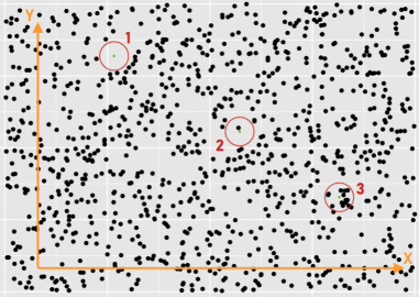
In the following example, the elevation of the three vertices (green dots) changed based on the scan points found within the specified search radius distance (red circles) along the vertex's Z axis as follows:
- 1 - No scan points were found, so a new elevation could not be computed. In this case, you have the option to ignore the vertex when moving the linear object, or interpolate a new elevation for the vertex, as described in step 6.
- 2 - Only one scan point was found, so the vertex's elevation changes to the elevation of that scan point regardless of the selected Search Strategy option.
- 3 - Multiple scan points were found, so the elevation of these points is taken into account when determining the vertex's resulting elevation based on the selected Search Strategy option.
- Optionally, when draping a linear object, do either or both of the following:
- Check the Offset lines check box, enter a distance, and specify the direction to offset the line horizontally when elevating it to the point cloud point.
- Check the Add point when interval exceeds check box and enter a distance for the interval between points in a CAD linear object that, if exceeded, will cause points to be created automatically.
- Optionally, when draping a linear object, do either of the following:
- Check the Interpolate missing elevations check box to specify that if no scan points are found within the specified radius of a vertex along its Z axis, the vertex's new elevation will be interpolated based on the slope between the previous and following vertices.
- Uncheck the Interpolate missing elevations check box to specify that if no scan points are found within the specified radius of a vertex along its Z axis, the vertex will be ignored and the new line will continue between the previous and following vertices with no interim vertex.
- Optionally, in the Layer drop-down list, select a different layer on which to display the new linework, or select to create a new layer.
- Optionally, check the Delete existing line check box to specify that the original line be deleted from the project after the new line is created.
Trajectories will never be deleted regardless the state of this checkbox.
- Click the Apply button to save the new line in the project.
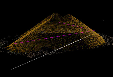
Following is an example of a new CAD line (magenta) that was created automatically by elevating an existing line (white) using the Drape Objects on Point Clouds command.