Annotate Objects
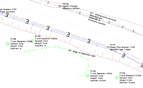
 The Annotate Objects command allows you to write text to screen for selected objects using multiple options to extract information. There is a Basic option for one off work and a Batch option that uses rule sets for repeatable work on large data sets.
Basic Tab
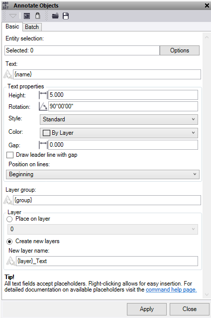
- Click in the Entity selection field and then in a graphic view select the objects which you want to annotate with text. Click Options for additional selection options.
- In Text, input the text to display on screen for the object and/or use the place holders to add text based on the object’s properties. Note: for the attribute placeholder {attribute x} input the attribute name in place of the x e.g. {attribute Diameter}. To place text on a new line use $$ before the text to be placed.
- Enter a Text height value.
- Enter a Text Rotation value.
- Select a Text style from the list or create a new one.
- Select a Text color
- Set the Text Gap to be used. This is the distance in metres that the insertion point of the text will be in the direction of rotation from the node it is created from. If you are using this to create 12d Vertex text, we recommend "0" offset.
- Check the Draw leader line with gap box to add a leader line when a gap has been used.
- Position on lines, sets the location for any text associated to lines being annotated. Note, that if you use the middle setting the text will be orientated to the line.
- Input a new Layer group name where you can use the placeholders to populate the name based on the object’s properties.
- Check the Place on layer option to place all the text created on an existing layer.
- Or check Create new layers and input a new layer name where you can use the place holders to populate the name based on the object’s properties.
- Click Apply to annotate the objects.
Batch Tab
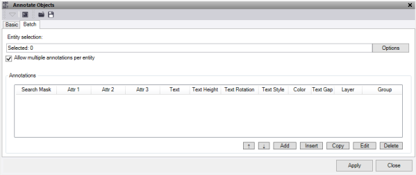
- Click in the Entity selection field and then in a graphic view select all the points and CAD objects you want to map. Click Options for additional selection options.
- Tick the Allow multiple annotations per entity if you need the same object to be read multiple times within the rule set. If this is not selected, then once an object has been selected in the rule set it will not be selected again even if the mask matches. Therefore, the order of the rule set is important.
- To import previous rule sets into your project from a .annotationrules file and populate the Annotations table, click the
 button at the top of the command pane and select the file you want to import.
 - To add Annotations to the bottom of the table, click the Add button to display the Edit Mapping dialog and do the following:
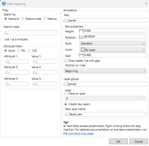
- Under Filter, in the Search mask field, enter all or part (using the wildcard asterisk "*") of the name/ID or feature code of the object you want to select.
- Name/Id – works on the name of a line, CAD block name or ID of a point.
- Feature code – works on the feature code of a point.
- Feature – works on the feature of a line, point, polygon or CAD block.
For example, if you enter *Fence* (preceded and followed by an asterisk), all objects with Fence in their name will be selected. This would include, for example, FrontFence1, FrontFence2, and RearFence1.
- Attribute filters can be applied to the mask as a secondary filter option. Select None, FXL, or 12D.
- Enter the Attribute name and Value you wish to search. Optionally, refine your search by adding another.
Once the mask is found true, it then checks the attributes. Ff they are found true it applies the annotations.
Note: these are decimal point sensitive.
- Under Annotation, enter the Text to display on screen for the object or use the place holders to add text based on the object’s properties.
Note: For the attribute place holder {attribute x}, input the attribute name in place of the x (for example, {attribute Diameter)}. To place text on a new line use $$ before the text to be placed.
- Enter a Height.
- Enter a Rotation.
- Select a Style from the list or create a new one.
- Select a Color.
- Set the Gap to be used. This is the distance in metres that the insertion point of the text will be in the direction of rotation from the node it is created from. If you are using this to create 12d Vertex text, we recommend "0" offset.
- Check the Draw leader line with gap box to add a leader line when a gap has been used.
- Position on lines sets the location for any text associated to lines being annotated.
Note: If you use the middle setting, the text will be oriented to the line.
- Input a new Layer group name where you can use the place holders to populate the name based on the object’s properties.
- Optionally, check Place on layer to place all the text created on an existing layer, or check Create new layers and input a new layer name where you can use the place holders to populate the name based on the object’s properties.
- Click OK to save the rule.
Your selections are displayed in a new row in the Annotations table in the Annotate Objects command pane.
To delete a row from the Annotations table, select the row and click Delete. To delete multiple rows, select the top row and hold shift and select the bottom row, then delete.
To move the row order, use the Up and Down arrows and to edit a previously entered row use the Edit button or double click on the row in the table. Note that the order of the mapping file matters as the command looks at the Name Mask from top to bottom. To reorder the file to alphabetical click on the "Search Mask" header.
To insert a row above an existing one click on the row location and press the Insert button. To copy an existing row, highlight the row and press the Copy button and this will be added directly below.
To export the contents of the Annotations table as rule sets into a ".annotationrules" file that can be shared with others, click the
 button at the top of the command pane and select a location for the new file.
 - Click Apply to apply the changes and keep the Annotate Objects command pane open.
The text annotations are applied to the selected objects and the number that were annotated is displayed.
Note: If the same object mask is selected in more than one row in the Annotate table, the mapping rules specified first will apply.
:
To add a placeholder, you must use one of the placeholder options. Using $$ in the operation will place any text written after it on a new line.
For example, the Text for the object could be:
- Current selected object:
- Name - "ITS Cable", Layer – "E COMM", Attribute – "Diameter = 100"
- Annotate object:
- Text "{name}$$Pipe Size {attribute Diameter}$$Unused"
- Results ITS Cable
- Pipe Size 100
- Unused
Note: This feature does not work on CAD points, blocks, or 3d objects.