Insert Alignment Table
 TheInsert Alignment Table command enables you to create a customizable table that describes the horizontal or vertical geometry that was used to create the selected alignment and display it in the plan view.
Use the Load and Save buttons at the top of the command pane there is the ability to load and save a settings file. Once you have populated the command with the appropriate settings you can save it in a file that can be reloaded in the future.
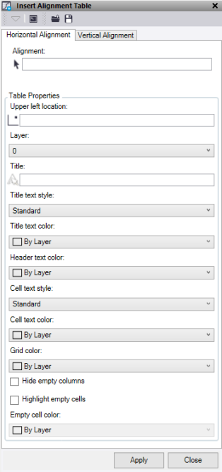
To Insert a Horizontal or Vertical Alignment:
- Select the Horizontal Alignment or Vertical Alignment tab. To insert both horizontal and vertical tables, set the Table Properties on both tabs and Apply them seperately.
- Click in the Alignment field, then in the graphic view or Project Explorer select the alignment string. A preview of the table data displays below the alignment selection field.
- To choose where the table is inserted, click in the Upper Left Location field and select a location by clicking in the graphic view, or enter the coordinates. This point is the bottom left corner of the Title row.
- Select a Layer, or select <new layer>.
- Optionally, enter a Title.
- Optionally, select a Title Text Style, or select <New text style>.
- Optionally, select a Title Text Color.
- Optionally, select a Header Text Color to give the column headers a color.
- Optionally, select a Cell Text Style, or select <New text style>.
- Optionally, select a Cell Text Color.
- Optionally, select the Grid Lines a colour.
- To hide columns with no values, click Hide empty columns.
- To highlight empty cells, click Highlight empty cells and select an Empty cell color.
- Click Apply to insert the table and turn on the appropriate layer to view.
Note: The Apply button works on the tab that is currently active.
Note: This command does not handle chainage equations.
![]()
