Insert Legend Table
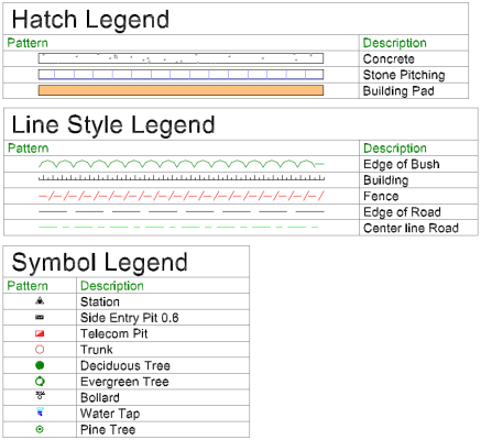
 The Insert Legend Table command enables you to create legend tables for hatches, line styles, and symbols using the definitions set up in an associated Feature library. Select data from the Project view and create a table containing one of each type displayed in the Plan view.
Use the Load and Save buttons at the top of the command pane there is the ability to load and save a settings file. Once you have populated the command with the appropriate settings you can save it in a file that can be reloaded in the future.
- Click in the Select Objects field, then in a graphic view select the lines, points, and hatches to use in the table. Click Options for additional selection options.
- Click Select to add one of each type to the appropriate table from the selected objects.
- Click Clear to remove all objects from the tables.
- Click the Hatches tab.
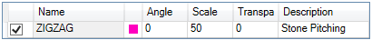
One of each hatches selected is displayed in the table. You can edit Angle, Scale, Transparency, and Description before creating the table. The default Description is populated by the pattern name of the Hatch. Uncheck any boxes that should not be displayed.
Note: This does not select user defined hatch patterns or CAD Hatches imported from .dwg files.
- Click the Line Styles tab.
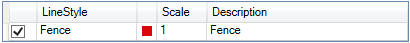
Each line style selected is displayed in the table. You can edit Scale and Description before creating the table. The default Description is populated from the line name unless the line has no name, in which case it is populated by the line style name. Uncheck any boxes that should not be displayed.
- Click the Symbols tab.
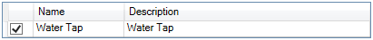
Each symbol selected is displayed in the table. You can edit Description before creating the table. The default Description name is populated from the symbol name. Uncheck any boxes that should not be displayed.
Note: This only selects and uses symbols found in the associated .fxl file.
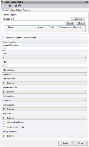
- Click the Hatches tab.
- Check the Allow user defined column widths box to set the width of the table columns manually instead of them being set using default widths and text scaling.
- To choose where the table is inserted, click in the Upper Left Location field and select a location by clicking in the graphic view, or enter the coordinates. This point is the bottom left corner of the Title row.
- Select a Layer, or select <new layer>.
- Optionally, enter a Title.
- Optionally, select a Title Text Style, or select <New text style>.
- Optionally, select a Title Text Color.
- Optionally, select a Header Text Color to give the column headers a color.
- Optionally, select a Cell Text Style, or select <New text style>.
- Optionally, select a Cell Text Color.
- Optionally, select the Grid Lines a colour.
- To hide columns with no values, click Hide empty columns.
- To highlight empty cells, click Highlight empty cells and select an Empty cell color.
- Click Apply to insert the table and turn on the appropriate layer to view.
Note: The Apply button works on the tab that is currently active.
Note: This command does not work with CAD Blocks.