Offset Slope
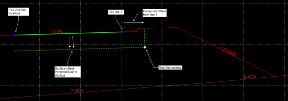
 The Offset Slope command enables you to create a new 3D line at an offset and elevation difference to a pair of lines or Ref line with nominated slope. The elevation of the new line is computed by extending the slope defined by the pair of lines and applying the elevation difference required. This tool is useful for extending pavement or subgrade strings.
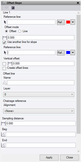
- Select a Reference Line. This is the line from which you want to extend the slope and offset distance. Optionally, change the selection highlight Color.
- Optionally, click Ref to select a line from Reference files.
- Select an Offset mode:
- Offset – Enter the horizontal offset distance that you require from the reference line.
- Line – Select a line to use for the horizontal offset distance from the reference line.
- Check Use another line for slope to use a second reference line to determine the slope value for the projected offset line.
- If you do not select this option, manually enter a single Slope % or ratio value to use. Enter a manual slope value in this format: -2% or -3:1, for example. The value will be converted to a slope ratio.
- Select a second Reference line. Optionally, change the selection highlight Color.
- Optionally, click Ref to select a line from Reference files.
- Check Vertical Offset to enter a perpendicular offset to the slope between line 1 and 2. While the elevation offset is computed perpendicularly to the slope between the two reference lines, it is applied vertically below the source and offset lines.
- If you do not check the box, manually enter a vertical offset to be applied to the reference line 1 and 2, and the computed offset line.
- Clicke Create offset lines to compute lines at the offset location of the source lines.
- Enter a Name for the new computed lines.
- Select or create a Layer for the new line to be placed.
- Select the Alignment that you wish to use for the computation of chainage intervals on which to calculate the offset lines. You will be computing the offset line locations perpendicular to the chosen alignment and using it for the chainage interval. If ‘None’ is selected, then the alignment used will be the first reference line selected at the top of the command.
- Sampling Distance – Enter the distance interval that you wish to use as the sampling interval for the offset line computations. If you enter a value of 0 here the computations will use the intervals between the nodes of the source lines.
- Enter an optional Beg (starting) chainage.
- Enter an optional End chainage.
- Click Apply to create line and keep the Offset Slope command pane open, or click Close to end and close the Offset Slope command pane.
(Typical Cross Section)