Slope-Slope Intersection
 The Slope-Slope Intersection command enables you to create new 3D lines at the intersection of two slopes defined by two pairs of lines, with or without vertical or perpendicular offsets. Use this tool to create subgrade strings at batter intersections.
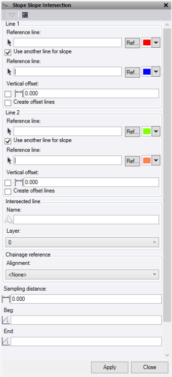
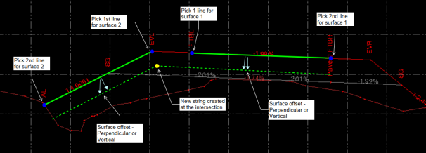
- Under Reference Line, enter the first line for the first slope element (typically defined by two lines or one line and a slope value). For example, if the first slope element is defined by the road centerline and the edge of pavement, pick the edge of pavement and then the road centerline as the second line. Optionally, change the selection highlight Color, or click Ref to select a line from reference files.
- To use a second line to define the slope, check Use another line for slope. To enter a slope value from the first line, leave this box unchecked.
- Check Reference Line to select the second line for the first pair of lines that will define the first of two slope surfaces for the computation. Optionally, change the selection highlight Color, or click Ref to select a line from reference files.
- If Slope is unchecked, enter a slope value from the reference line to define the first of two slope surfaces.
- Optionally, check Vertical Offset, then enter a perpendicular offset to the slope between line 1 and 2. While the elevation offset is computed perpendicularly to the slope between the two reference lines, it is applied vertically below the source lines.
- If you do not check Vertical Offset, enter a vertical offset to be applied to the slope between reference line 1 and 2.
- Check the Create offset lines to compute lines at the offset location for the source lines.
- The settings for Line 2 is the second slope to be used in the intersection. Follow the same process as line 1
- Enter a Name for the new computed lines.
- Select or create a Layer for the new line to be placed.
- Select the Alignment to use for the computation of chainage intervals on which to calculate the offset lines. This computes the offset line locations perpendicular to the chosen alignment and uses it for the chainage interval. If you select None, the alignment will be the first reference line from the line 1 selection.
- Under Sampling Distance, enter the distance interval to use as the sampling interval for the offset line computations. If you enter a value of 0, the computations use the intervals between the nodes of the source lines.
- Under Beg, enter an optional start chainage.
- Under End, enter an optional end chainage.
- Click Apply to create line and keep the Slope-Slope Intersection command pane open, or click Close to end and close the Slope-Slope Intersection command pane.
Note: This command is licenced to Survey Intermediate and above and does not require an ANZ Toolbox licence.
(Typical Cross Section)