Run a String Conformance Report
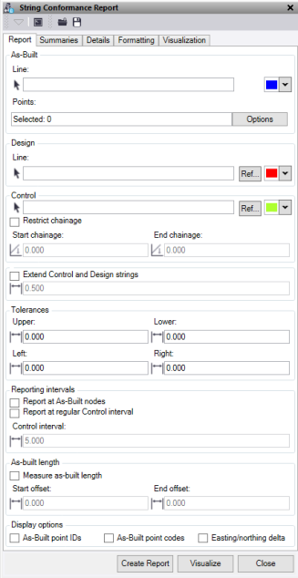
 The String Conformance Report command is to report as-built strings against a design string such as Kerb, barrier, drainage, and walls. It includes options for summary display and an option to visualize output in plan-view prior to creating report.
Click Load or Save at the top of the command pane, then populate the command with the appropriate rule sets and save it in a file that can be reloaded in the future.
Report tab
|
As-Built |
Select an as-built line string to use in the report (optional). Optionally, change the selection highlight color. Note: The highlight color does not work on pipe strings. |
|
Pipe Level |
Select the justification required for reporting. |
|
As-Built Points |
Optionally, select as-built points to use in the report. |
|
Design |
Select the design line to report against. This line can be the same as the control. Optionally, change the selection highlight color. Click Ref to select the line from Reference files. |
|
Vertical offset |
Specify a vertical adjustment to apply to the design line string. |
|
Pipe Level |
If you've selected a Pipe string, choose the justification required for reporting. |
|
Control |
Required field: Select the control alignment to report chainage and offset. Optionally, change the selection highlight color. Click Ref to select the line from Reference files. |
|
Restrict chainage
|
Check to restrict chainages between the Start chainage and End chainage specified. |
|
Extended Control and Design strings |
Check to extend the design and control line strings to report points just past the end of the specified the distance. |
|
Tolerances Upper tolerance
|
Enter the vertical and horizontal tolerance values to check the as-built against. |
|
Report As-Built nodes |
Check if you want to report only the nodes on the as-built line string. Note: You must have one of these reporting interval options selected if using an as-built string. |
|
Report at regular Control interval |
Check to report at regular intervals you specify in Control interval along the as-built line string. |
|
Measure as-built length Start offset End offset |
Check to report the endmost as-built locations against the end of the design string for length. Use the start and end offsets to adjust the design length location reported against. This reports the As-built and Design grade between the endmost location. Note: these lengths are measured along the Control alignment. |
|
Include As-Built point IDs |
Check to include as-built point IDs in the report |
|
Include As-Built point codes |
Check to include as-built point Codes in the report |
|
Include easting/northing delta |
Check to include the easting/northing delta in the report. |
Summaries tab
|
Select header summaries to include |
Check the summary fields to include in the report. |
Details tab
|
Title |
Enter a title for the report (for example, the project name). |
|
Custom image file |
Select a .png or .bmp image file to add to the top right corner of the report (for example, a company Logo or project image). This only appears if you have a Title. |
|
Description |
Enter a description for the report. |
|
Reference number |
Enter a survey job reference number. |
|
Author |
Enter the name of the report's author. |
|
Custom Header |
Enter a user defined heading. |
|
Custom Text |
Enter a user defined text to go beside the Custom header. |
Formatting tab
|
Colors |
Choose the colors to use in the Excel Report.
|
Visualization tab
|
Create visualization layers |
Check to display conformance information on layers in TBC. |
|
Layer prefix |
Enter a prefix to add to layer names. |
|
Text Height |
Select the height of the text to be displayed on screen. |
|
Text Style |
Select the text style for the text displayed on screen. |
|
Gap |
This is the distance in metres that the insertion point of the text will be right or left of the node it is created for. |
|
Draw leader line with gap |
Check to add a leader line when a gap has been used. |
|
Clear visualization layers |
Check to clear the layers before adding new data. |
|
Include data prefix |
Check to include the data type as a prefix to the text on screen. |
|
Data and prefixes |
Check the boxes for the data you need to see on screen, and to adjust the prefixes.
|
|
Colors |
Choose the color of the conformance text to be displayed. |
|
Align text square to line |
Draw text perpendicular to the Control line selected. |
