Shrink 3D Faces
If you use a mesh of 3D faces to create a surface, any vertices that exist at the same horizontal location, but which have different elevations, will create vertical 3D faces in the resulting surface. You will know that you need to 'shrink 3D faces' when you see flags at surface vertices and messages in the Flags pane stating that "The vertex has been ignored. It is directly above another vertex."
To fix this, 'shrink the 3D faces' to form closed, triangular breaklines slightly inset (.5 mm) from each selected face. These breaklines can then be used to create a surface that closely approximates the original mesh of 3D faces.
This can be helpful in forming a valid surface from data incorporating vertical faces or when coincidental 3D face vertices that have differing elevations at the same location.
Note: This command is primarily used to fix data from applications that allow points with different elevations at the same horizontal location.
|
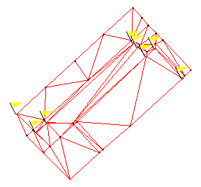
Initially, the surface is formed using vertical 3D faces with coincidental vertices, resulting in two elevations at these vertices. This data is not valid for forming a surface. |
|
|
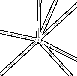
The non-vertical 3D faces are shrunk to create triangular breaklines (shown in black) with offset vertices which can be used to form the surface. |
|
|
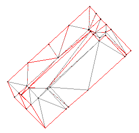
Using the new breaklines, the surface is properly formed with a single elevation at each vertex. |
|
Prerequisites:
- Surface with vertical faces
To 'shrink 3D faces' for a surface:
Follow these steps immediately after you receive one or more flagged messages that a vertex is directly above another vertex in a surface. If you cannot undo the surface creation because you have performed other commands in the interim, you will need to delete the surface and start with step 2 below.
- Select Undo. The surface disappears.
- If the command pane is not already displayed, select Command Pane, or press . The Command Pane displays.
- Click Shrink 3D Faces in the All Commands list, or type
shrink3dfacesin the Command box at the top of the pane and press . The Shrink 3D Faces command pane displays. - In the Plan View, pick the 3D faces that you want to use to form a surface.
- Select the layer on which you want the new breaklines to reside in the Layer for breaklines box.
Note: You will select the data on this layer to use when you create the surface. If necessary, create a new layer by selecting <<New Layer>>.
- Click . The breaklines are created within each selected triangular, 3D face.
To create a surface from the newly created breaklines:
- Select View Filter Manager in Views > View. The View Filter Manager displays.
- If necessary, click the
 icon to collapse each group except Layers.
 - Uncheck the box for each group to hide the data.
- In the Layers group, right-click the name of layer you created the 3D face breaklines on, and select View Only This from the context menu. All of the other layers in the group are unchecked so that only the breaklines are visible.
- Select all of the breaklines in the graphic view, and select Create Surface in Surfaces > Create.
- Follow the instructions for creating a surface.
