Calculation sensors
Calculation sensors can be used to produce a calculated scalar data stream based on the inputs of one or more sensors.
To define a new calculation sensor:
-
Click the Add Sensor menu item or click the Add Sensor button
 on the Sensor Listing page. The Create Sensor page appears:
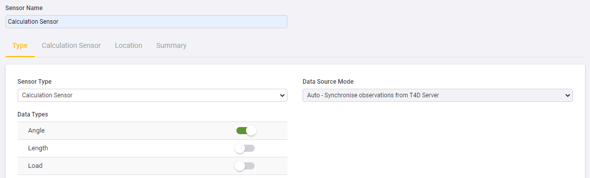
From the Sensor Type drop-down list, select Calculation Sensor and then select an output Data Type. A calculation sensor can be linked to only one output data type.
-
Click Next to proceed to the Calculation Sensor tab:
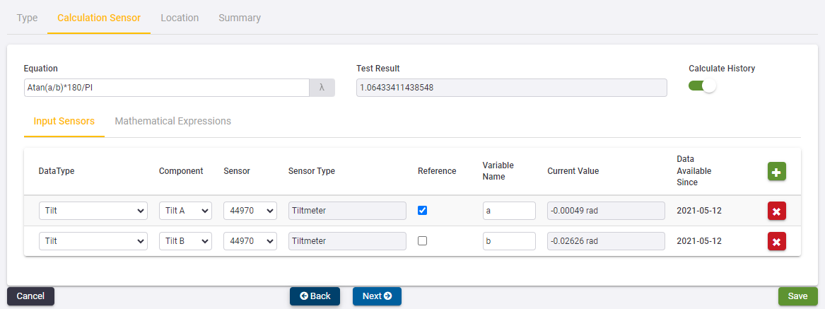
Use the Calculation Sensor tab to configure complex calculations.
-
In the Equation field, you can type in the equation of the calculation you have in mind.
-
For a list of supported expressions and operations, click the Mathematical Expressions subtab.
-
If the project already contains other calculation sensors, then click the λ button next to the Equation field to quickly re-use equations.
-
The Input Sensors sub tab contains a grid where any number of input sensors can be defined.
-
To add an input sensor, click the Add button
. -
When you choose a Data Type then the Component and Sensor drop-down lists are populated accordingly. When the Sensor is selected then the Sensor Type field is automatically populated and the Current Value is extracted from the database.
-
By default, the Variable Names associated with each input are designated as “a”, “b”, “c”, “d”, and so on. These variables can however change to match the variable names as they appear in the Equation at the top of the page.
-
-
Each time that you change either the equation or any of the inputs, the software attempts to calculate a Test Result. This attempt must succeed before you can add the calculation sensor.
-
To calculate the values for all data up to the Data Available Since date, enable the Calculate History toggle.
The Current Value, the actual Calculation and the Test Result are in terms of SI Units. In the example above, the Test Result value is in Radians. However, once the sensor has been configured the output data stream will be presented in the display unit selected for the project.
-
-
You must set one of the inputs as the Reference input. This input, along with the settings on the next tab will determine when the calculation will take place.
-
-
Click Next to proceed to the Synchronization tab:
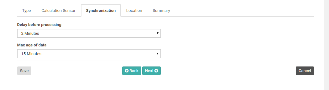
Calculation sensors can accept inputs from different sensors and these sensors may deliver data at different intervals and with various degrees of latency. This can complicate the logic with regard to when and with what to calculate a new output.
-
The Delay before processing value applies to the Input Sensor that has been flagged as the Reference. When a new observation from the Reference Input Sensor becomes available, then T4D will wait for the specified Delay before processing time before attempting a calculation.
-
When the Delay before processing time expires, T4D looks for the latest available observation from all other Input Sensors. If observations can be found for all these sensors, and if none of these observations are older than the Max age of data, then the calculation is performed and the output is generated.
-
The timestamp on the output corresponds to the timestamp of the observation that came from the Reference Input Sensor.
-
-
Click Next to proceed to the Location tab:
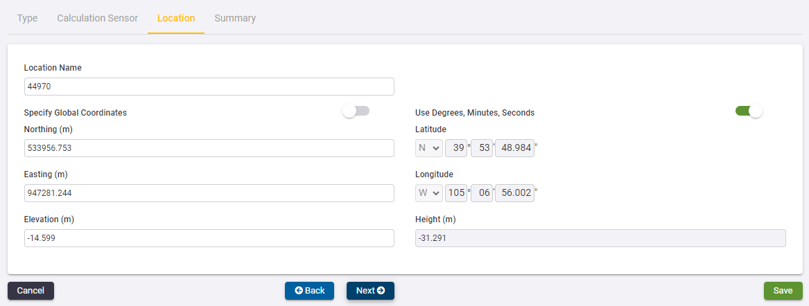
On the Location tab, you must specify a Location Name and the Coordinates of the sensor location.
-
If you already have other Locations defined in the project then you can select an existing Location.
-
The Grid Coordinates are shown on the left of the page. If you are not using a Local Coordinate System, then the Global Coordinates are shown on the right.
-
If you edit the Grid Coordinates then the Global Coordinates will update accordingly. Alternatively you can click the Specify Global Coordinates toggle to disable the Grid Coordinate fields and enable the Global Coordinate fields. If you edit the Global Coordinates then the Grid Coordinates will be updated automatically.
-
Global Coordinates can be entered in Degrees, Minutes and Seconds or in Decimal Degrees. Toggle the switch above the Global Coordinate fields to switch between entry modes.
-
-
Click Next to proceed to the Summary tab to verify the sensor configuration:
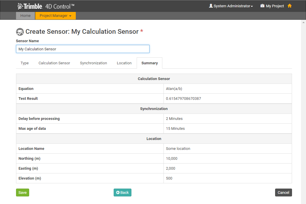
Verify that all the settings are correct.
-
Specify a name for the Calculation Sensor and then click Save.
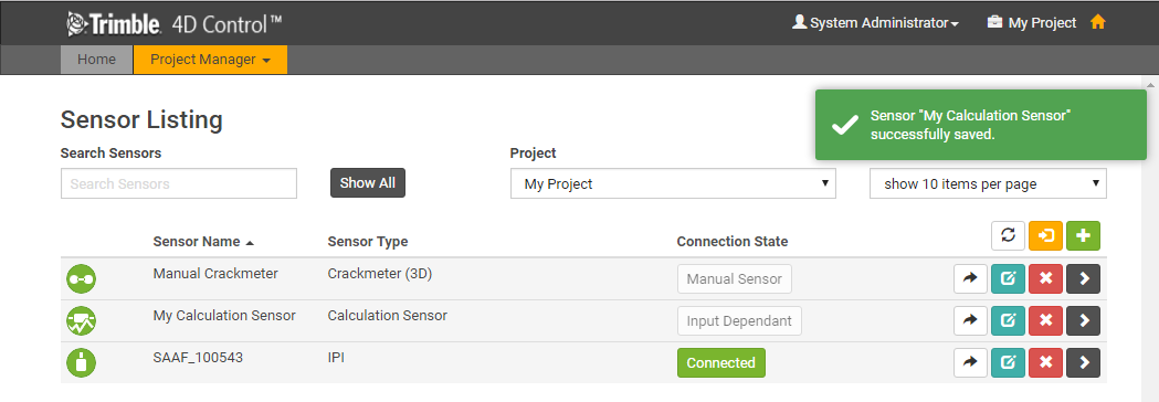
The calculation sensor is added to the project and the Sensor Listing tab appears.
