Geotechnical sensors
Trimble 4D Control supports a variety of geotechnical sensors. Before adding geotechnical sensors to a project, you must configure the required data loggers in T4D Server. For details on how to configure a data logger in T4D Server, refer to the T4D Server help files.
The following geotechnical sensor types are supported by default:
-
Crack meters
-
Data loggers
-
Earth pressure cells
-
Extensometers
-
Hygrometers
-
Inclinometers
-
Load cells
-
Piezometers
-
Rain gauges
-
Soil moisture content sensors
-
Strain gauges
-
Tiltmeters
-
Water level gauges
-
Weather stations
You can also define additional custom geotechnical sensor types.
To add a new geotechnical sensor to the project:
-
Click the Add Sensor menu item or click the Add Sensor button
 on the Sensor Listing page. The Create Sensor page appears:
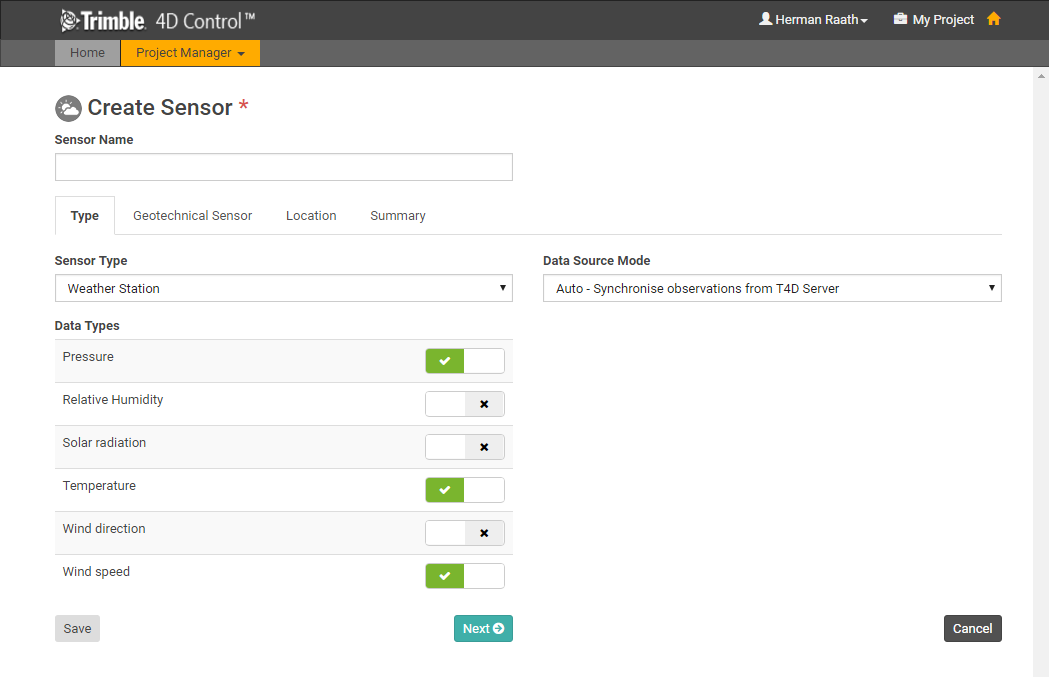
When the page first loads only the Type tab is visible. The other tabs will appear as soon as a Data Type is linked to the sensor.
-
Use the Type tab to select the sensor type and link data types from T4D server:
-
In the Sensor Type field, select the appropriate type of geotechnical sensor.
-
In the Data Types group, click the check boxes to link the appropriate Data Types to the new sensor.
-
-
Click Next to move to the next tab or click the next tab to select it.
-
The drop-down list at the top of the Geotechnical Sensor tab lists all the geotechnical sensors configured in T4D Server, but filtered according to the selected data types:
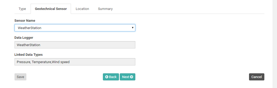
If you have not yet entered a name for the sensor in the Sensor name field at the very top of the page, then the name defaults to the selected entry.
Details of the Data Logger module and the linked data types are displayed in the remaining fields on the Geotechnical Sensor tab.
-
Click Next to proceed to the Location tab:
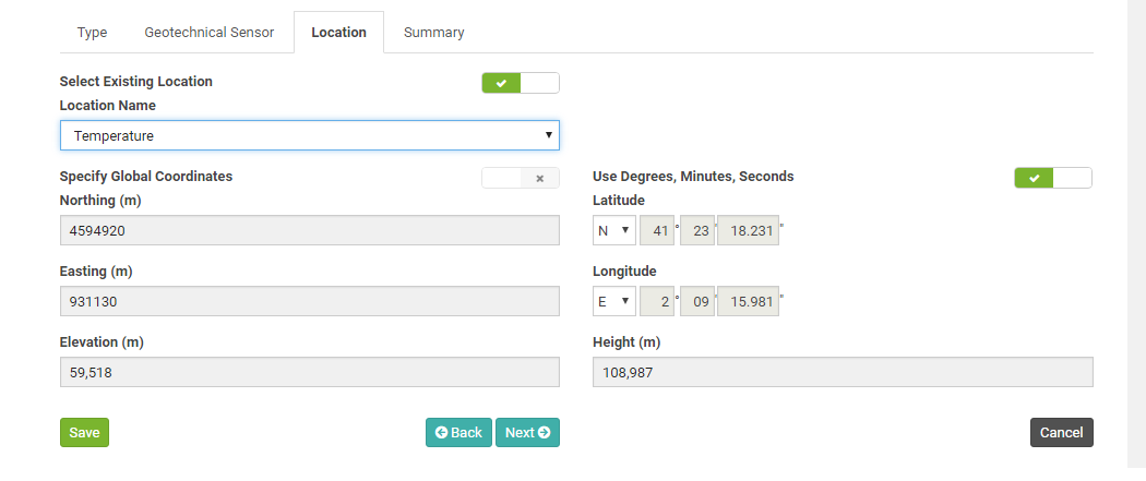
On the Location tab, you must specify a Location Name and the Coordinates of the sensor location.
-
If you already have other Locations defined in the project then you can select an existing Location.
-
The Grid Coordinates are shown on the left of the page. If you are not using a Local Coordinate System, then the Global Coordinates are shown on the right.
-
If you edit the Grid Coordinates then the Global Coordinates will update accordingly. Alternatively you can click the Specify Global Coordinates toggle to disable the Grid Coordinate fields and enable the Global Coordinate fields. If you edit the Global Coordinates then the Grid Coordinates will be updated automatically.
-
Global Coordinates can be entered in Degrees, Minutes and Seconds or in Decimal Degrees. Toggle the switch above the Global Coordinate fields to switch between entry modes.
-
-
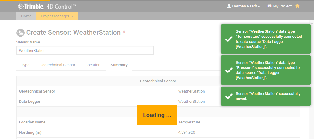
Click Next to proceed to the Summary tab to verify the sensor configuration:
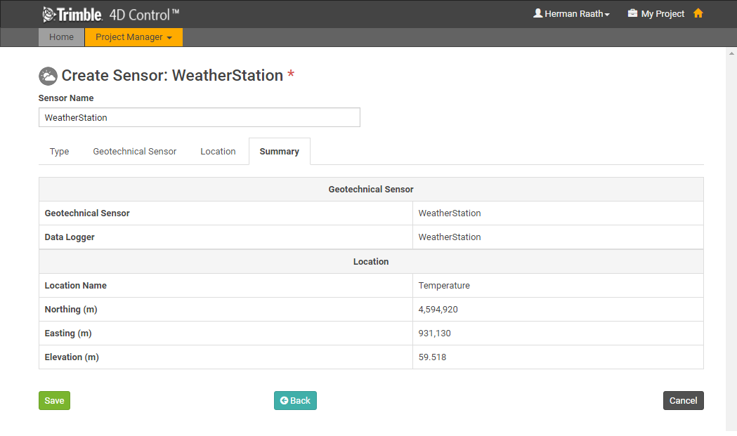
Verify that all the settings are correct and if required edit the name.
-
Click Save.
The geotechnical sensor is added to the project and connected to the selected data sources.
-
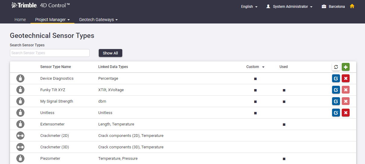
To define a new geotechnical sensor type, from the Project Manager menu at the top of the screen, select Geotechnical Sensor Types.
A list of the existing geotechnical sensor types is shown.
-
An indicator in the Custom column indicates the sensor type is a Custom sensor type. By default the list is sorted to display Custom sensor types at the top of the list. Only Custom sensor types can be edited.
-
An indicator in the Used column indicates if the sensor has ever been used.
-
Only Custom sensor types that have never been used can be deleted.
-
-
To define a new custom geotechnical sensor type, click the
button. -
In the Sensor Type Name field, specify a name for the new sensor type.
-
Select the Data Types to be associated with the new sensor type.
-
In the Display As field, you can enter an alias to be used for each linked Data Type.
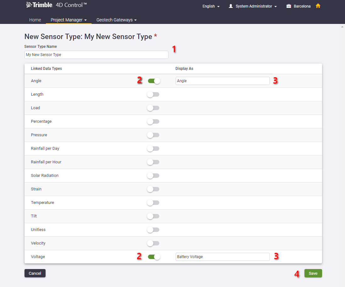
-
Click Save.
The new geotechnical sensor type is created, and is available from the Sensor Type drop-down list on the Add Sensor page.
