Rotation angles
GNSS receivers and target displacement sensors produce an observation time series of displacements broken down into Northing, Easting and Height components.
The structure that is being monitored may not align with the direction of Northing and/or Easting as defined in the Coordinate System used. Rotation Angles can be used to configure these sensors so that planar component of the displacement is broken down into Radial and Tangential components as well.
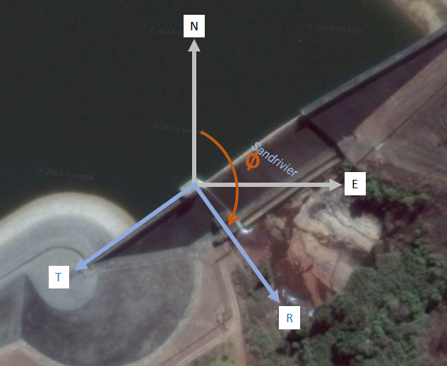
The following image depicts a typical example of how the Radial/Tangential axis pair might be configured. During configuration the user specifies a rotation angle (Ø), which is the angle from the Northing axis to the Radial axis, measured in a clockwise direction.
In this case the Rotation Angle is configured so that the bearing of the positive Radial axis corresponds with the downstream direction of the dam structure.
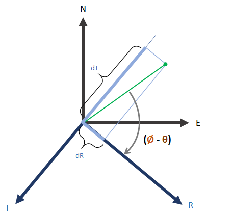
The diagrams below show the mathematical relationship between the displacement components in the Northing and Easting directions and the displacement components in the Radial and Tangential components.
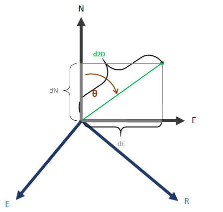
Let us assume a hypothetical example where the Rotation Angle (Ø) between the Northing axis and the Radial axis is 120° and where a prism is displaced by 3 mm in the Northing direction and 4 mm in the Easting direction.
Given the above, the following will hold:
| Value | Symbol | Calculation |
|---|---|---|
| Axis Rotation | Ø | User Defined = 120° |
| Planar Displacement Magnitude | d2D | d2D = √(dN² + dE²) = √(3² + 4²) = 5 mm |
| Azimuth of the Displacement | θ | θ = ArcTan(dE/dN) = ArcTan(4/3) = 53.13° |
| Northing Displacement | dN | dN = d2D.Cos(θ) = 5.Cos(53.13°) = 3 mm |
| Easting Displacement | dE | dE = d2D.Sin(θ) = 5.Sin(53.13°) = 4 mm |
| Radial Displacement | dR |
dR = d2D.Cos(Ø - θ) = 5.Cos(120°- 53.13°) = 1.964 mm |
| Tangential Displacement | dT |
dT = d2D.Cos(Ø - θ + 90°) dT = d2D.Sin(θ - Ø) dT = 5.Sin(53.13°- 120°) dT = - 4.598 mm |
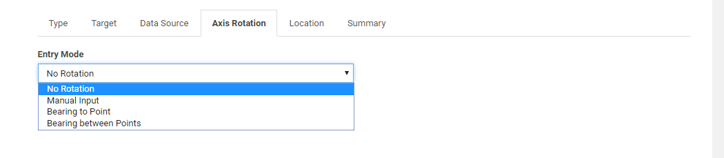
Where applicable, the Add Sensor page includes an Axis Rotation tab. The input fields on this tab are used to configure the bearing of the Radial axis (and by implication the bearing of the Tangential axis) as described in the example above.
There are four different modes that can be used to define the Rotation Angle.
No Rotation
The No Rotation option applies a rotation angle of zero degrees. In this case the direction of the Radial axis coincides with the Northing axis and the direction of the Tangential axis coincides with the direction of the Easting axis.
Manual Input
The Manual Input mode allows for manual entry of the rotation angle.
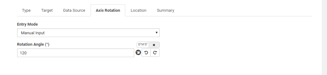
The Angular Unit Preference as defined in the Project Unit Preferences applies. If the Angular Unit Preference is set to degrees, then toggle switch denoted with D°M’S” appears above this Rotation Angle field. Use this toggle switch to switch between Decimal Degrees and Degrees, Minutes and Seconds.
The arrow icon  next to the Rotation Angle field depicts the direction of the Radial axis. The reference orientation for this depiction is such that the Northing axis points up and the Easting axis points right. This holds regardless of the true orientation of the Coordinate System.
There are two utility buttons for rotating the current rotation angle by 90 degrees in the CCW and CW directions: 
Bearing to Point
The Bearing to Point entry mode can be used to calculate the Rotation Angle so that the Radial axis will coincide with a line drawn from the Coordinate of the sensor that is being configured to the specified Point.
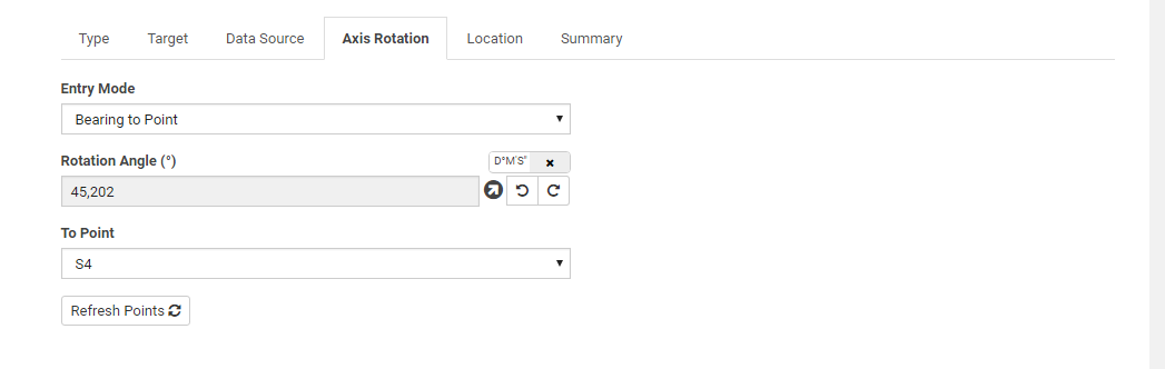
The To Point drop-down list contains all total stations, prisms and GNSS receivers configured in T4D Server.
You can still click on the Rotate CCW and Rotate CW utility buttons. The rotation angle will be adjusted accordingly and the Entry Mode changes to Manual Input.
Bearing between Points
The Bearing between Points entry mode can be used to calculate a Rotation Angle so that the bearing of the Radial axis will correspond with the bearing of a line drawn between to the specified Points.
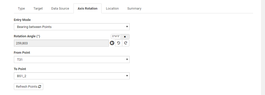
The From Point and To Point drop-down lists contain all the total stations, prisms and GNSS receivers configured in T4D Server.
You can still click on the Rotate CCW and Rotate CW utility buttons. The rotation angle will be adjusted accordingly and the Entry Mode changes to Manual Input.
