GNSS antenna height measurement
This topic describes how to measure the height of an antenna mounted on a range pole when the Measured to field is set to Bottom of antenna or Bottom of antenna mount. With a fixed height range pole, the height is a constant value.
When measuring or staking out points using IMU tilt compensation, make very sure the entered antenna height and measurement method is correct. Alignment reliability and pole tip position reliability, especially during movement of the antenna while the pole tip is stationary, relies completely on the antenna height being correct. Residual error in horizontal position caused by antenna motion while measuring when the pole tip is stationary cannot be removed by changing the antenna height after measuring the point.
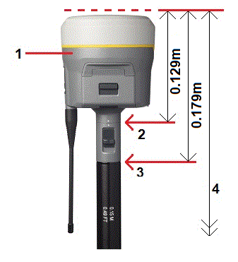
Refer to the following diagram where (1) is the receiver, (2) is the bottom of the antenna mount, (3) is the bottom of the quick release, (4) is the corrected height to the APC from the bottom of the pole.
The following describes how to measure the height of a receiver using the lever on the receiver extension, when the receiver is mounted on a tripod.
Refer to the following diagram where (1) is the receiver, (2) is the lever of the extension, (3) is the corrected height to the APC from the ground mark and (4) is the uncorrected height.
Refer to the following diagram where (1) is the Trimble GNSS receiver, (2) is the corrected height to APC and (3) is the uncorrected height of 1.80m.
If this receiver is mounted on a tripod, measure the height to the bottom of the groove between the gray base and the white top of the antenna, and select Center of bumper in the Measured to field.
If you are using a fixed height tripod, you can measure the height to the bottom of the antenna housing and select Bottom of antenna mount in the Measured to field.
Refer to the following diagram where (1) is the Zephyr antenna, (2) is the corrected height to APC and (3) is the uncorrected height.
If this antenna is mounted on a tripod, measure the height to the top of the notch on the side of the antenna.
If this antenna is mounted on a tripod, measure the height to the bottom of the notch on the side of the antenna.
Refer to the following diagram where (1) is the Tornado antenna, (2) is the corrected height to APC and (3) is the uncorrected height.
If this antenna is mounted on a tripod, measure the height to the join between the gray and white plastics on the antenna.
Refer to the following diagram where (1) is the Microcentered antenna, (2) is the corrected height to APC and (3) is the uncorrected height.
If this antenna is mounted on a tripod, measure the height to the bottom of the plastic housing. Enter this value in the Antenna height field and set the Measured to field to Bottom of antenna.
If the Microcentered antenna (or a Compact L1/L2 antenna) has a groundplane measure to the underside of the notch in the groundplane.
Refer to the following diagram where (1) is the Microcentered L1/L2 antenna, (2) is the groundplane, (3) is the underside of the notch and (4) is the top of the notch.
Measure the height to three different underside notches around the perimeter of the groundplane. Then record the average as the uncorrected antenna height.
