Tunnel survey settings and tolerances
The available fields depend on the survey method.
To improve performance when surveying, configure the EDM timeout field if it is available. If the instrument struggles to get a measurement due to, for example, reflective or dark surfaces, increase the EDM timeout. This setting is not available when connected to a Trimble SX10 scanning total station because the EDM times out automatically.
- Enter the Start point name, Point code, and Scan interval. Points to be scanned are defined by the scan interval, and include the start and end points that define each element in the template surface.
- Use the On station adjustment option to control where the position will be measured when the tunnel surface does not match the design. If selected, Auto OS appears at the top left of the screen. You must specify a station tolerance if using this option. See On station adjustment.
- When measuring manually with a prism, select the Apply target height perpendicular to profile option. This option enables a position to be measured perpendicular to the tunnel profile when using a prism by entering the prism radius as the target height. See Position measurements using a prism.
- If you are using a Trimble VX spatial station, select the VX scanning option for improved scanning performance.
-
Select Instrument perspective profile display to display the tunnel profile in the direction the instrument is facing. This option is especially useful when you are facing in the direction of decreasing station, as the tunnel profile is then displayed in the same sense that the instrument is pointing, rather than always assuming you are facing in the direction of increasing station.
- Set the Point name and Point code.
- When measuring manually with a prism, select the Apply target height perpendicular to profile option. This option enables a position to be measured perpendicular to the tunnel profile when using a prism by entering the prism radius as the target height. See Position measurements using a prism.
-
Select Instrument perspective profile display to display the tunnel profile in the direction the instrument is facing. This option is especially useful when you are facing in the direction of decreasing station, as the tunnel profile is then displayed in the same sense that the instrument is pointing, rather than always assuming you are facing in the direction of increasing station.
- Enter the Start point.
-
If you are setting out all blast holes, enter the Start delay and Mark delay values to control the automated set out process. The Start delay gives you time to walk to the location of the first point to be marked. The Mark delay is the length of time, in seconds, that the laser point flashes once the position is found.
The Mark delay is the length of time, in seconds, that the laser pointer flashes once the position is found.
When a position is found within tolerance, the Mark point event sounds and:
- If the instrument has a tracklight, the laser pointer and the tracklight flash for the period defined in the Mark delay field.
- If the instrument is a Trimble SX12 scanning total station, the laser pointer changes to solid and the Target Illumination light (TIL) flashes for the period defined in the Mark delay field.
-
Select Instrument perspective profile display to display the tunnel profile in the direction the instrument is facing. This option is especially useful when you are facing in the direction of decreasing station, as the tunnel profile is then displayed in the same sense that the instrument is pointing, rather than always assuming you are facing in the direction of increasing station.
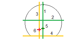
For all survey methods you can display guide lines in the cross section view. Select:
- Display profile vertical centerline to display a vertical green line through the alignment or, if the alignment has been offset, the offset alignment.
- Display spring line to display a horizontal green line through the alignment or, if the alignment has been offset, the offset alignment.
- Display alignment vertical centerline to display a vertical orange line through the alignment.
- Display floor line to display a horizontal orange line through the alignment or, if the alignment has been offset, the offset alignment.
The spring and floor lines can be offset vertically (up and down), relative to the alignment or, if the alignment has been offset, the offset alignment.

1
Profile vertical centerline
2
Spring line (offset vertically from the offset alignment)
3
Alignment vertical centerline
4
Floor line (offset vertically from the offset alignment)
5
Offset alignment
6
Alignment
The available fields depend on the survey method.
- For Auto scan, set the Station,Overbreak and Underbreak tolerances, and the number of Iterations.
- For Position in tunnel, set the Overbreak and Underbreak tolerances.
- For Set out, set the Position tolerance and the number of Iterations. See Set out position tolerance.


