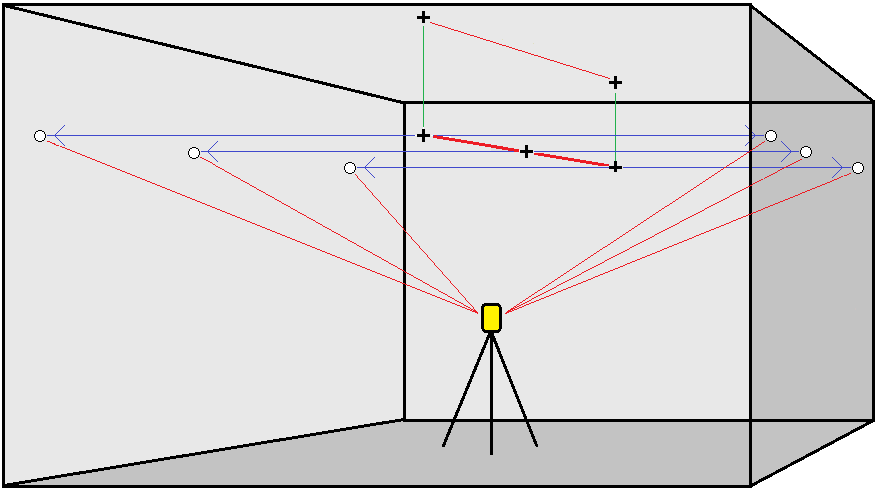
To auto stake laser lines from a centerline
Automatically stake out laser lines offset from a centerline. The laser lines are defined at regular intervals at right angles relative to the centerline.
- To create the centerline:
- In the map, select the line(s) and then tap Auto stake / Laser lines offset from CL.
Tap
 and select Auto stake / Laser lines offset from CL and select the start and end points.
When selecting points, select them from the map or tap
 for other selection methods.
To reverse the direction of the line, tap Swap.
- Then:
- Define an Interval for staking the line.
- If required, define offsets. The centerline can be offset by a:
- Vertical offset – applied above or below the centerline
Station offset – applied backward or forward along the centerline
These offsets are used to calculate the design positions.
- To extend the centerline, enter the extension distance in the Extend beyond end point field. To shorten the centerline, enter a negative value in this field.
- Tap Next.
- Review the defined laser lines. Select and delete any lines that do not require staking. Tap Next.
- Enter values for the Point details and Settings, or accept the default values. Tap Next.
- To aid in the auto stakeout of the laser lines you are prompted to aim and measure a position on the right side of the mine. Repeat when prompted for the left side.
-
Tap Next.
The Mines software stakes all the points on the left, starting with the first line and finishing on the last. It then stakes all the points on the right side, starting with the last line and finishing on the first..
TIP – If the instrument fails to point in the correct direction, during the Start delay period, you can manually point the instrument in the correct direction.
The software will use the previous position to reduce the number of iterations required to find the next position. However if a position is not found within tolerance the software will use the design position of the previous position to reduce the number of iterations required to find the next position.
-
When a position is found within tolerance, the Mark point event sounds and:
- If the instrument has a tracklight, the laser pointer and the tracklight flash for the period defined in the Mark delay field.
- If the instrument is a Trimble SX12 scanning total station, the instrument changes to STD mode and the laser pointer stops flashing and moves to position itself at the EDM location. The laser pointer changes to solid while the Target Illumination light (TIL) flashes for the period defined in the Mark delay field. When the point is stored the instrument automatically returns to TRK mode and the laser pointer resumes flashing.
At the end of the Mark delay period the instrument auto stakes the next point. Tap Pause to temporarily halt the auto stake process. Use the Prev and Next softkeys to skip to the previous or next point.
-
While the software is iterating to find a point within tolerance of the target, tap Pause to temporarily halt the iteration process. The software switches the instrument to tracking mode and shows the stakeout deltas, which indicate the direction the instrument EDM needs to go to reach the target. A value shown in red indicates the deltas are out of tolerance. Use the arrow keys on the controller or the arrow keys on the video screen to move the instrument EDM closer to the target. Once the delta values are shown in black tap Store to store the record, restart the auto stakeout sequence, and move to the mark point step.
-
If a point within tolerance cannot be found, the point is skipped.
-
-
When the process has finished, the Results screen shows the number of points staked and the number of points skipped.
