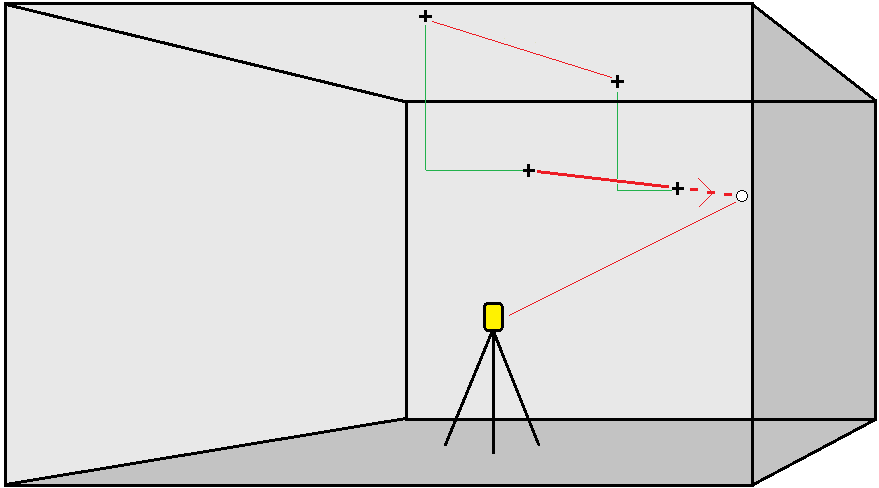
To project a line
Automatically stake out projected line points at an offset from your laser line to create a new reference line between the laser line and the mine face.
- To create the line:
- In the map, select the line and then tap Auto stake / Project line.
Tap
 and select Auto stake / Project line and select the start and end points.
When selecting points, select them from the map or tap
 for other selection methods.
To reverse the direction of the line, tap Swap.
- If required, define offsets. The projected line can be offset by a:
- Horizontal offset – applied left or right of the line
- Vertical offset – applied up or down from the line
- Tap Next.
- Enter values for the Point details, Position tolerance, and Settings or accept the default values. See Auto stake settings. NOTE – Position tolerance values refer to the tolerance when searching for the next position on the mine surface. Position tolerance in this context does not refer to the precision or accuracy of the measured point. Tap Next.
-
Tap Next.
TIP – If the instrument fails to point in the correct direction, during the Start delay period, you can manually point the instrument in the correct direction.
The instrument turns to the design point, measures a position and then checks this position against the defined tolerances. If it is outside the tolerances it turns to a new position and repeats the process until a position within tolerance is found, or the maximum number of iterations is reached.
The software will use the previous position to reduce the number of iterations required to find the next position. However if a position is not found within tolerance the software will use the design position of the previous position to reduce the number of iterations required to find the next position.
-
When a position is found within tolerance, the Mark point event sounds and:
- If the instrument has a tracklight, the laser pointer and the tracklight flash for the period defined in the Mark delay field.
- If the instrument is a Trimble SX12 scanning total station, the instrument changes to STD mode and the laser pointer stops flashing and moves to position itself at the EDM location. The laser pointer changes to solid while the Target Illumination light (TIL) flashes for the period defined in the Mark delay field. When the point is stored the instrument automatically returns to TRK mode and the laser pointer resumes flashing.
At the end of the Mark delay period the instrument auto stakes the next point. Tap Pause to temporarily halt the auto stake process. Use the Prev and Next softkeys to skip to the previous or next point.
-
While the software is iterating to find a point within tolerance of the target, tap Pause to temporarily halt the iteration process. The software switches the instrument to tracking mode and shows the stakeout deltas, which indicate the direction the instrument EDM needs to go to reach the target. A value shown in red indicates the deltas are out of tolerance. Use the arrow keys on the controller or the arrow keys on the video screen to move the instrument EDM closer to the target. Once the delta values are shown in black tap Store to store the record, restart the auto stakeout sequence, and move to the mark point step.
-
If a point within tolerance cannot be found, the point is skipped.
-
-
When the process has finished, the Results screen shows the number of points staked and the number of points skipped.
