Stakeout deviation check
In a fabrication environment, use the User coordinate system and Deviation check workflow to measure the position of an element and receive real-time deltas relative to the user coordinate system (UCS) rather than the instrument. This iterative process allows for precise adjustment of heavy components before permanent welding.
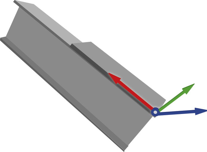
The image below shows a practical example of how a UCS might be placed to assist accuracy when conducting a weld on a beam. UCS enables a temporary, movable grid that acts as a custom origin. By defining the origin and axes relative to a specific object, all reported deviations relate directly to the orientation of that object. The image below shows an example of how a UCS might be placed to assist with accuracy when conducting a weld on a beam.
NOTE – The stakeout deviation check and user coordinate system features are available with the Object Oriented Setup software option. To purchase a license, contact your local Trimble Distributor.
 Define the user coordinate system
-
Tap
 and select Stakeout / Deviation check.
 -
Tap the Set UCS softkey.
-
Select the method for defining the user coordinate system:
-
Points: Select the origin point, a point on the X-axis, and a point on the horizontal axis.
-
Lines: Select the line or edge along the X-axis and the line or edge along the Y-axis.
-
Manual: Key in coordinates to edit the origin and rotation values. If a previous UCS exists, the last saved UCS is shown. If not, the axis appears at the center of the model.
-
Load: Select a previously saved UCS.
-
-
Enter the Name of the user coordinate system.
-
Define the Orientation of the user coordinate system:
-
Point method:
-
Select the origin point.
-
Select a point on the X-axis.
-
Select a point on the horizontal axis.
-
-
Line method:
-
Select line/edge along X-axis.
-
Select line/edge along Y-axis.
-
-
Manual method:
-
If a previous user coordinate system has been created in the Job, when selecting the manual method the last saved UCS will display, and the origin and rotation values can be edited.
-
If no previous UCS has been created, the axis will display at the center of the model.
-
-
Load the recently saved UCS or select a previously saved UCS from the drop down list.
-
-
Review the user coordinate system results, including Origin coordinates and Rotation information for each axis.
-
To change these values, manually override the numbers in the fields.
-
To invert the orientation, tap the Flip softkey to rotate the Z-axis 180°.
-
-
Tap Accept to set and store the user coordinate system.
-
Select the points to measure on the object using one of the following:
-
Map selection
-
List
-
Wild card search
-
Key in
-
Find
-
-
Select the measurement method.
TIP – To change between Laser (DR) and Prism, tap the
icon in the status bar to view the Instrument functions screen and then tap the Target button to switch between active prism types or select Target DR. The instrument then automatically turns to the point location and tracks the target or laser. -
Review the deviations: The deviation check workflow displays the difference between the measured component and the design in terms of the defined user coordinate system (DX, DY, DZ).
-
Use the softkeys to manage your points:
-
To add additional points, tap the + Point softkey.
-
To modify a point, tap Edit.
-
To remove a point from the list, tap Delete.
-
To check another point in your list, select it and the instrument automatically turns to that position.
-
-
Tap Store to save the deviation check results for that user coordinate system.
