Current position information
Information on the current position and, if applicable, its relationship to the selected set out position appears below the plan view or cross section view.
To show or hide deltas, tap and hold in the delta display area of the screen. In the Deltas list, tap a delta to change whether the delta is displayed. A check mark indicates the delta will be shown. To reorder the deltas, tap and hold a delta and drag it up or down the list. Tap Accept.
If, when measuring without a prism, your current position (displayed as a cross) fails to update, then ensure the Apply target height perpendicular to profile option from Settings is not selected.
To scroll through the values, tap the arrow to the left of the text. Refer to the diagrams and the table below for a description of the information that may appear.
| Number | Value | Description |
|---|---|---|
|
– |
Station |
The station of the current position, calculated along the 2D distance of the tunnel design. |
| – | Distance along Alignment | The slope distance from the start of the alignment to the current position. |
|
– |
Underbreak/Overbreak |
The underbreak or overbreak of the current position in terms of the selected template surface. Appears in red if it is out of tolerance. |
|
– |
Rotation |
The rotation value of the cross section at the current position. |
|
– |
Delta station |
The difference between the station of the current position and the station of the target. |
|
– |
Delta offset |
The radial difference between the measured position and the set out position. Appears in red if it is greater than the Position tolerance. |
|
– |
Rotation |
The rotation value of the cross section at the current position. |
|
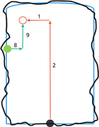
1 |
H.Offset |
The horizontal offset of the current position from the alignment (shown as a red cross). If the alignment has been offset, the horizontal offset is from the offset alignment (shown as a smaller green cross). |
|
2 |
V.Offset |
The vertical offset of the current position from the alignment (shown as a red cross). If the alignment has been offset, the vertical offset is from the offset alignment (shown as a smaller green cross). May be either perpendicular or true vertical, depending on the template position options in the Tunnel design. |
|
3 |
Profile dist. |
The profile distance of the current position measured along the selected template surface from its start point. |
|
4 |
Hz. off. (rot) |
The horizontal offset of the current position from the rotated alignment (shown as a green cross) and rotated with the tunnel. |
|
5 |
Vt. off. (rot) |
The vertical offset of the current position from the rotated alignment (shown as a green cross) and rotated with the tunnel. Maybe either perpendicular or true vertical, depending on the template position options in the tunnel design. |
|
6 |
Dist. to vertex |
The profile distance from the vertex (7) to the current position. The vertex (shown as a black line) is defined by the intersection of a perpendicular line from the rotated alignment (shown as a green cross) to the tunnel roof. |
|
8 |
Δ H.Offset |
The difference between the horizontal offset of the projected line of the pipe or blast hole and the current position measured by the instrument. |
|
9 |
Δ V.Offset |
The difference between the vertical offset of the projected line of the pipe or blast hole and the current position measured by the instrument. |
|
– |
Northing |
Northing of the current position. |
|
– |
Easting |
Easting of the current position. |
|
– |
Elevation |
Elevation of the current position. |
