Set out position requirements
Set out positions typically define bolt hole or drill hole locations within the tunnel, and are also used to define blast holes in the tunnel face or holes for installing pipes. All set out positions are defined by the station range, offset values, and method. The station range can be defined as a single station or multiple stations with defined start and end stations.
You can key in set out positions as part of the tunnel definition using the Set out screen in Trimble Access. Alternatively, you can design the set out positions in Trimble Business Center and then save them as a TXL file for use in Trimble Access, or you can import set out positions from a CSV file. To key in or import set out positions, see To add set out positions.
Setting out positions using Trimble Access Tunnels refers to the process of staking out the designed positions, and physically marking the location of set out points on the tunnel surface so that drilling equipment can be guided to the correct location of each point for drilling the hole and installing the bolt or pipe. See To set out predefined positions.
 Set out position methods
Supported types of set out positions are:
- End-face blast holes
- Bolt holes using the following methods:
- Radial
- Horizontal
- Vertical
- Multiple radial
- Pipes
Refer to the following diagram:
1
Blast hole
2
Radial
3
Horizontal
4
Vertical
5
Multiple radial
6
Alignment
7
Offset center
8
Interval
9
Pipes
Blast hole set out
Refer to the diagram below to set out positions for blast holes.
1
Blast hole position
2
Design position
3
Design surface
4
Tunnel surface
5
Tunnel alignment
Bolt hole set out
Refer to the diagram below to set out positions for bolt holes defined by the radial (including multiple radial), horizontal, and vertical methods.
1
Set out position defined radial
2
Set out position defined horizontal
3
Set out position defined vertical
4
Design position
5
Design surface
6
Tunnel surface
7
Center for radial position
Pipe set out
Set out pipe positions to install an arch of pipes that extend lengthwise along the planned tunnel alignment to reinforce the roof of the working area. Typically, a series of regularly spaced and overlapping arches of pipes (a pipe umbrella or canopy tube) are installed throughout the sequential excavation of the tunnel.
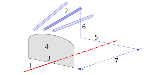
1
Alignment
2
Pipe umbrella
3
Horizontal offset (pipe start)
4
Vertical offset (pipe start)
5
Horizontal offset (pipe end)
6
Vertical offset (pipe end)
7
2D distance along the alignment.
Imported set out position requirements
NOTE – You cannot import Multiple radial set out points.
The required format for the CSV file is:
StartStation, EndStation, Type, HorzOffset, VertOffset, Code, Direction, Surface, ExtraHorzOffset, ExtraVertOffset, Length.
See the following examples for the format for each set out method:
| Set out positions | Method | Values | Example |
|---|---|---|---|
|
End face blast holes |
Blasthole |
StartStation, EndStation, Type, HorzOffset, VertOffset, Code |
40,60,Blasthole,0.5,‑0.5,Blast hole |
|
Radial bolt holes |
Radial |
StartStation, EndStation, Type, HorzOffset, VertOffset, Code, Direction, Surface, HorzCenter, VertCenter |
0,40,Radial,‑3.2,2.2,Bolt hole,,S2,1.05,0.275 |
|
Horizontal bolt holes |
Horizontal |
StartStation, EndStation, Type, HorzOffset, VertOffset, Code, Direction, Surface |
0,20,Horizontal,,3.1,Bolt hole,Right,S2 |
|
Vertical bolt holes |
Vertical |
StartStation, EndStation, Type, HorzOffset, VertOffset, Code, Direction, Surface |
0,,Vertical,3.2,,Bolt hole,Up,S2 |
| Pipes | Pipe |
StartStation, EndStation, Type, HorzOffset, VertOffset, Code, EndHorzOffset, EndVertOffset, PipeLength |
0,,Pipe,‑1.0,2.5,Pipe,-1.1,2.6,5.0 |
NOTE –
- The Surface name, Code, Horizontal offset, and Vertical offset values are optional.
- If no Surface name is specified, or the Surface name is not applicable for the specified station range, the first template surface suitable for the station range is used.
- The Method value must be one of the following: Blasthole, Horizontal, Vertical, Radial, Pipe.
- The Direction value must be one of the following: Up, Down, Left, Right, or empty (for a radial offset, blast hole, or pipe).
