Create a Project
-
Open WorksOS.
-
Select your account, and click Apply.
-
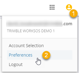
Click your Profile icon and select Preferences.
-
Set preferences for:
-
Date and time formats and the time zone (of the project location)
-
Location display and WorksOS interface language
-
Units for measure (distance), pressure, temperature, and number format
-
Currency for cost data
-
-
Click Save.
-
Click the Projects icon in the main left Nav Bar.
-
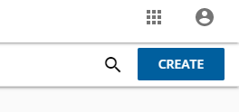
Click the CREATE button in the upper-right corner.
-
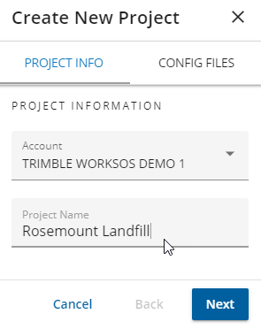
In the Create New Project pane > PROJECT INFO tab:
-
Confirm your account or select a different one to create the project in (this is the same account used for WorksManager).
-
3D Enabled - this a project that is intended to have machine productivity (.tag file) data processed into it. 3D-enabled type projects are used primarily in WorksOS, but still have full project functionality in WorksManager.
-
Non-3D-enabled - this is a project that is not intended to have machine productivity (.tag file) data processed into it. It will still have full project functionality and will primarily be used there.
-
Enter a Project Name; this must be unique among all projects in the selected account
-
Confirm your account or select a different one to create the project in (this is the same account used for WorksManager).
-
Enter a Project Name; this must be unique among all projects in the selected account.
-
select the Project Type. There are 2 types of projects.
-
-
Click NEXT and select either 3D-enabled or Non-3D-enabled in the Project Type list.
-
Click NEXT and then FINISH on the bottom right toolbar to complete the new project setup. At this point, these project attributes are validated; if any fails, the project is not created:
-
Project name is unique for the account.
-
Project calibration (coordinate system) file is valid.
-
-
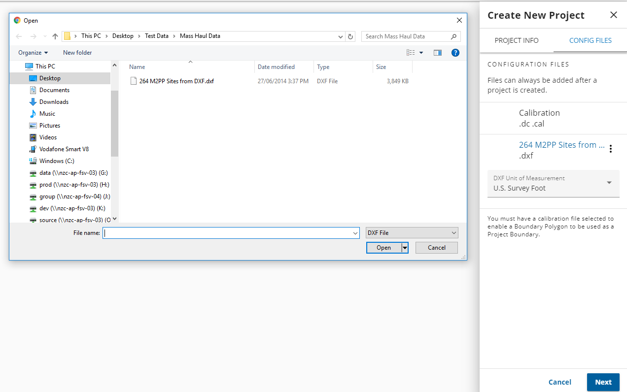
Click Next to proceed to the CONFIG FILES tab.
-
Click + next to Calibration .dc .cal.
-
Browse to and add a coordinate system/site calibration file for the project.
-
Calibration files are required for WorksOS 3D-enabled projects in order for machine productivity data (.tag files) to be processed into the project. To ensure data and location accuracy, the file should be the same calibration file as the machines in the field are using.
-
Typically, you will draw a project boundary in the next step, but you can optionally upload the boundary for a project as a .dxf file. Click + next to Boundary .dxf and browse to a .dxf with the boundary.
-
Optionally, add a boundary for the project as a DXF file. Click + next to Boundary .dxf and browse to a .dxf that includes the boundary.
-
Then select the unit of measurement the DXF file was created in to ensure a correct project location and projection on the map in WorksOS.
-
Note: A .dxf file containing multiple boundaries can be uploaded. Currently, WorksOS automatically selects the first boundary it finds in the .dxf file. It is recommended that you select a .dxf file containing a single boundary.
-
Click Next to proceed to the DRAW BOUNDARY tab.
-
Pan and zoom into the location of the job site.
-
3D-enabled project boundaries are yellow.
-
Non-3D-enabled project boundaries are blue.
-
Pick points in the Map view to draw a polygonal boundary representing the extents of the site, and double-click to close the final segment. You can edit an existing project boundary by clicking-and-dragging a point. If you need to undo a point, click the Undo icon.
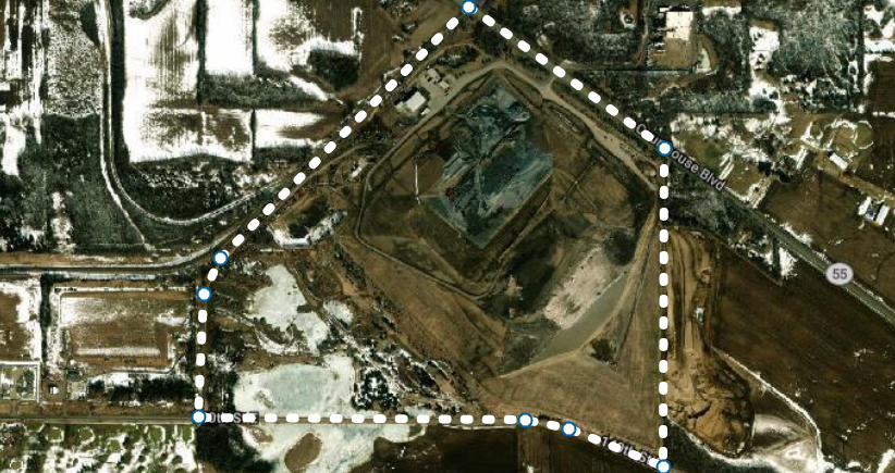

This boundary is used as a ‘geo-fence’ that determines whether your field devices and machines are ‘on site’. The boundary must represent the true location of the project and encapsulate all areas where machines are running with the intention of having their data collected.

-
Pick points in the Map view to draw a polygonal boundary representing the extents of the site, and double-click on the first point to close the boundary.
This boundary is used as a ‘geo-fence’ that determines whether your field devices and machines are ‘on site’. The boundary must represent the true location of the project and encapsulate all areas where machines are/will be running with the intention of having their data collected.
If you uploaded a .dxf boundary in the previous CONFIG FILES step, the polygon it contains is displayed on the map as the pre-selected project boundary. No further steps are required. A .dxf boundary cannot be edited.
However, non-3D-enabled project boundaries can overlap any other boundary without issue, so you can have projects that overlap in time and space as long as only one of them is 3D-enabled.
-
Click the Dashboard icon on the left navigation bar.
-
Once you have drawn or uploaded a polygonal boundary from a .dxf file, you click NEXT and then FINISH on the bottom-right toolbar to complete the new project setup. At this point, these project attributes are validated; if any fails, the project is not created:
-
Project name is unique for the account.
-
Project calibration (coordinate system) file is valid.
