Using Tiltrotators
TIP – For optimum performance when using Autos features, avoid connecting the Operator App device to the system via Wi-Fi. Ensure that you use a wired connection.
A tilting rotating coupler (tiltrotator) enables you to:
- Rotate the attachment to any angle.
- Tilt the attachment up to 40° from a normal fixed‑attachment position, at any rotation angle.
In the display's layout views, the appearance of a tiltrotator attachment is different to that of a standard attachment.
Plan view
For the plan view, the perspective does not change when the attachment rotates.
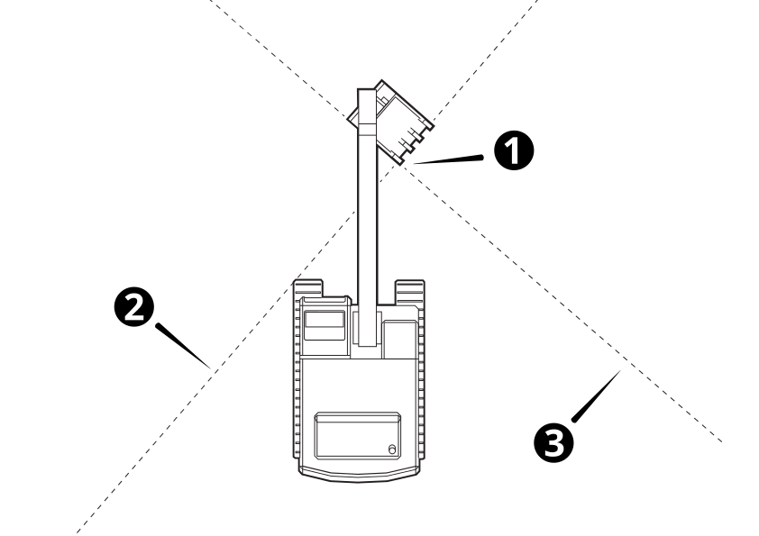
- The attachment (1) rotates independent of the machine heading.
- The cross section line (2) rotates with the attachment. It is parallel to the cutting edge.
- The profile line (3) rotates with the attachment. It is perpendicular to the cutting edge.
Cross section view
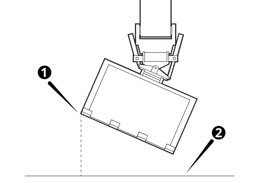
- The cross section view is aligned to the attachment heading (perpendicular to the cutting edge) and rotates with the attachment (1)
- The cross section line (2) runs along the design surface underneath the cutting edge and rotates with the attachment (1).
NOTE – In the Overlays screen if you turn on visibility of the machine, it will not apply to this view as the machine could block the view of the attachment while it is rotating.
Profile view
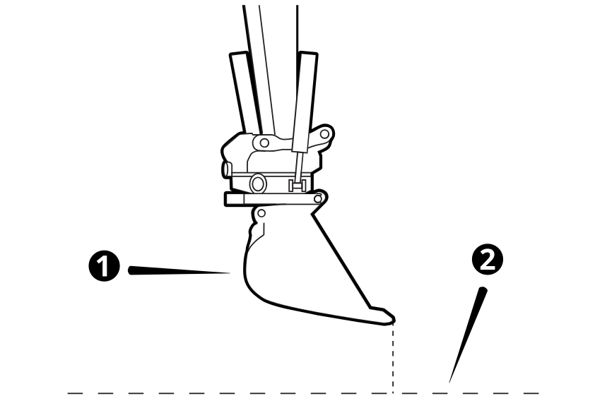
- The profile view is aligned perpendicular to the attachment heading and rotates with the attachment (1).
- The profile line (2) runs along the design surface underneath the focus point, in the direction of the attachment heading.
NOTE – In the Overlays screen if you turn on visibility of the machine, it will not apply to this view as the machine could block the view of the attachment while it is rotating.
3D view
For the 3D view, the perspective does not change when the attachment rotates. The profile and cross section lines rotate with the attachment.
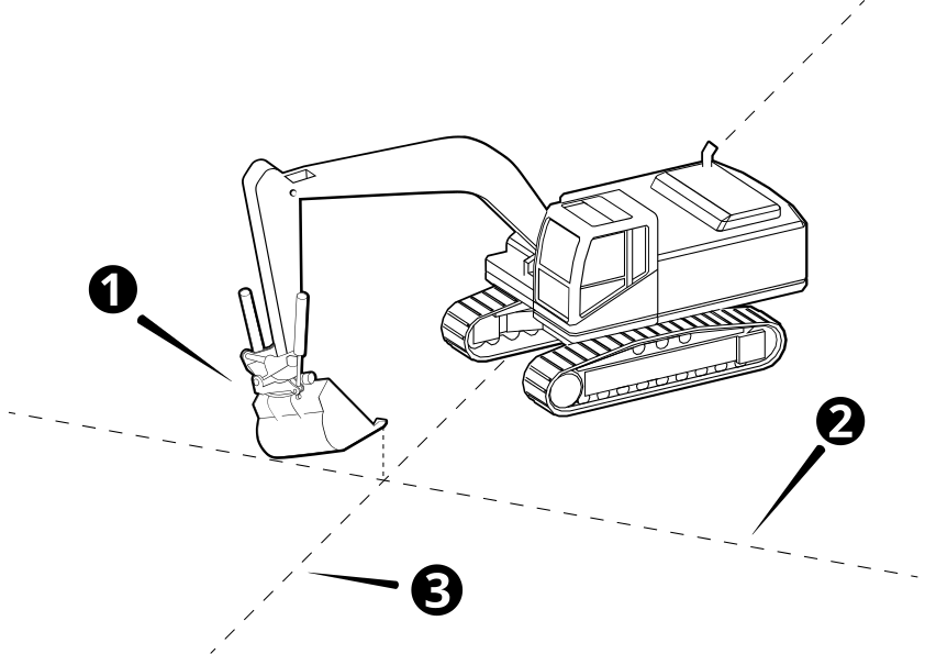
- The attachment (1) rotates independently of the machine heading.
- The cross section line (2) runs along the design surface underneath the cutting edge and rotates with the attachment (1).
- The profile line (3) runs along the design surface underneath the focus point, in the direction of the attachment heading.
Useful text items
Text items display information on the work screen. When you use a tiltrotator the following text item is available: Attachment Rotation.
