Using the AR camera
To use the Augmented Reality (AR) camera:
- Install the hardware. Refer to the Excavator Cab Install Guide within the Excavator Hardware Install Manual.
- Install the license. Refer to the Configuration Guide within the Excavator Commissioning Manual.
- Enable the camera in the Web Interface's Install Assistant. Refer to the Excavator Cab Install Guide within the Excavator Hardware Install Manual.
- Set the camera feed to display on a view pane.
- Calibrate the camera in the Operator App.
Supported operation
- The camera is available on excavator systems.
- The camera is supported on TD520 displays in any screen layout mode. For the best experience, assign the camera to a larger pane.
- The camera is not supported on Bring Your Own Display (BYOD).
- The camera is not supported for guidance using an HS410 heading sensor.
- You cannot zoom the view in or out when using the camera.
Setting the camera feed to display on a view pane
- Do one of the following:
- Touch and hold on the work screen. When the pop-up menu displays, tap Layout.
- Tap the System Settings
 button and then tap Layout.
- Set one of the panes to AR Camera view
 .
.
Calibrating the AR camera
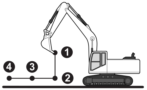
To calibrate the camera, the system requires you to move the attachment to 4 different positions:
1 Linkage raised, attachment high on the screen and fairly close to the cab
2 Linkage lowered, stick vertical and attachment close to the ground
3 Linkage extended to mid reach, attachment close to ground
4 Linkage extended to full reach, attachment close to ground
Step 1: Establish an active guidance solution
The calibration process requires an active guidance solution. On the dashboard, ensure that a design is loaded and there are no red tiles before beginning the calibration sequence.
Step 2: Complete the calibration sequence
- Do one of the following:
- Tap the Open icon
 on the Machine Setup screen.
 - From the System Settings menu, select Calibrate AR Camera.
The first Calibrate AR Camera screen displays.
- Tap the Open icon
- Read the instructions and tap Next.
- Move the linkage until the attachment is in the position indicated onscreen.
- On the display, drag a corner of each target until they are aligned with the left and right corners of the cutting edge.
- Tap Set:
- The targets' positions are locked in place.
- A tick displays beside the targets.
- Two new targets appear.
- Repeat Steps 3 to 5 for three more attachment positions.
- Tap Save. The work screen displays showing the AR camera view.
AR camera calibration best practice
WARNING – If the machine enters an avoidance zone during camera calibration, the operator does not receive a warning. Avoid calibrating the AR camera when the machine is near an avoidance zone.
- Avoid moving the machine body during calibration. If the camera position changes during calibration, restart the process.
- During calibration, align the four pairs of targets to the exact position of the attachment corners as accurately as possible. The point positions affect display accuracy.
- For optimum performance, use a straight edged attachment.
- If the cutting edge is wider than the body of the attachment, align the targets to the width of the cutting edge.
- Similarly, if the attachment has teeth, align the targets to the cutting end of the teeth.
- In general, align the targets to the widest part of the attachment and the forward-most part of the attachment. You may need to use a set square or project lines from the cutting edge and attachment side to place the target correctly if the corners are curved.
- For best performance, ensure the TD520 display has firmware OS 4.19.20 or higher.
- Avoid using the camera with an HS410 heading sensor.
TIP – The camera calibration data is saved in a .machine file. If you can access the web interface, save a .machine file when you complete the calibration. This way, if you reload the .machine file it includes the calibration.
AR camera settings
When the AR camera is calibrated, it is ready for use.
To adjust the visibility settings, touch and hold the eye icon  in the upper right corner of the work screen. You can adjust:
- Cutting Edge visibility: Turns the cutting edge overlay on or off.
- Design Transparency: Controls the transparency level of the design and grid lines. Move the slider to the right to make the design and grid lines more solid.
- Brightness: Controls the brightness of the camera feed. Move the slider to the right to increase the brightness.
To adjust the visibility of other features that appear on the screen, select the Overlay screen.
Re-enabling the camera
If the AR camera is accidentally disconnected:
- Reconnect the camera cables.
- Wait for the camera to turn on and reconnect.
- Move the attachment to confirm that the camera is operating correctly. If it is not, restart the calibration process.
On some occasions, you may need to restart the EC520 controller.
Troubleshooting
-
When you use the AR camera with an overlapping design, the AR view on the work screen may look incorrect.
- If the camera view becomes corrupted during calibration, exit the wizard and then return.
- If the camera view stops working during operation, change to a different view on the Layout screen. Then change back to the AR Camera view.
- If you suspect the camera mount has moved, repeat the calibration process.
- If the overlay grid lines do not match the design, or the cutting edge overlay does not align with the actual cutting edge, repeat the calibration process.
- It is possible to complete the calibration without moving the linkage, but the overlay position will be incorrect. Ensure you move the linkage to the position indicated at each stage of the calibration.
- If guidance is lost during calibration, the Next button becomes unavailable.
- For best performance, use landscape orientation for the camera and portrait orientation for the system display.
-
If you downgrade the system to an earlier firmware version (for example, v1.11), you must disconnect the SD510 harness from the EC520 harness first. If the SD510 harness remains connected, machine files will fail to load.
