Vertical Guidance
The system calculates the amount of cut/fill between the attachment tips and the design surface (or an extension of it) and displays that in the text items and lightbars to guide the operator to build the design surface.
The vertical guidance option selected in the Attachments screen changes how the system looks at and extends the design surface beneath the blade to calculate the cut / fill values, so it is important that the correct selection is made for the task you are performing.
This guide will help you understand how the different vertical guidance options work and why you should choose them so that you can determine when you change the selection.
Overcut Protection is also available.
Access the Attachments screen
Perform one of the following actions to access the Attachments screen:
-
Open the Machine Setup tile on the Dashboard and then tap the Attachments button.
-
Open the Work Settings menu
 and tap Attachment Manager.
 -
Touch and hold the Focus shortcut icon
 on the shortcut bar.
The Attachments screen
Use the Attachments screen to:
- Select a focus, or a side of the attachment, to guide to. For more information on using the guidance focus, see Horizontal Guidance.
-
Select a Vertical Guidance
-
Optionally apply a Custom Inset
-
Optionally toggle Overcut Protection on
-
Edit cutting edge length
Select an option for Vertical Guidance
- Access the
- Select Guidance Focus. For more information on using the guidance focus, see Horizontal Guidance.
- Select the Vertical Guidance option for the current task:
- Right - a single vertical guidance point inset 0.200 m (7.9 inches) from the right cutting edge tip. Use this option when you are using the right side of the cutting edge to build a design that is less than half your blade width, such as a narrow ditch.
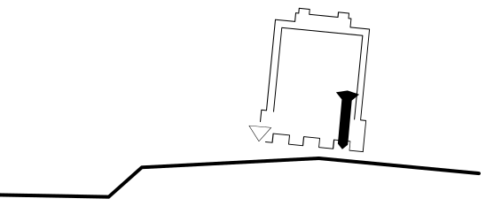
- Center - a single guidance point in the cutting edge center. Use this option when you need to grade material over a change in grade, such as the crown or shoulder of a road. You can extend up to half the blade over the change in grade.
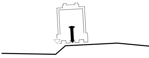
- Left - a single vertical guidance point inset 0.200 m (7.9 inches) from the left cutting edge tip. Use this option when you are using the left side of the cutting edge to build a design that is less than half your cutting edge width, such as a narrow ditch.
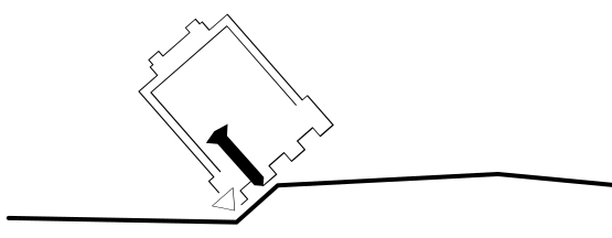
- Linked to focus - a single guidance point inset 0.200 m (7.9 inches) from the cutting edge tip with focus. Use this option when you are building a design that is less than half your cutting edge width, such as grading a narrow ditch from both directions. This guidance point is linked to the Focus and changes when the Focus changes.
- 2 Points - two vertical guidance points, each inset 0.200 m (7.9 inches) from the cutting edge tip. Use this option when you need to average the grade over the cutting edge width, such as when grading a design with smooth curves, like a golf course.
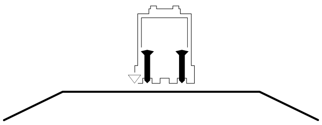
- Right - a single vertical guidance point inset 0.200 m (7.9 inches) from the right cutting edge tip. Use this option when you are using the right side of the cutting edge to build a design that is less than half your blade width, such as a narrow ditch.
- Tap Select.
Design line preview
The system can show an indication of the current design line in the cross section view. This enables you to identify how the cut/fills are being calculated based on the currently-selected vertical guidance point (or points) and the Overcut Protection setting:
-
Access the Overlays screen.
-
Enable the Design Line Preview (Cross Section) toggle. The design line displays on the cross section view as a dashed line.
Apply a custom inset
A custom inset allows you to change the position of the vertical guidance points by entering a custom offset distance from the cutting edge tips.
NOTE – The custom inset option is available only when using Linked to Focus and 2 Points Vertical Guidance options.
To apply a custom inset:
- Select either Linked to Focus
- Open Advanced Options and toggle Custom Inset on.
- Optionally update values in one or both of the inset fields. The insets swap sides when the Focus changes.
- Optionally, toggle Overcut Protection on.
- Tap Select.
Overcut Protection
If Overcut Protection is on, the system checks for overcut of the design surface and adjusts the cut/fill guidance to prevent it.
The Overcut Protection check depends on the selected Vertical Guidance:
-
When vertical guidance
-
When 2 Points vertical guidance is selected, only the tips of the cutting edge are checked against the design surface.
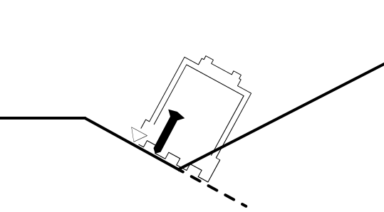
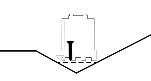
Overcut Protection is useful when moving material across the toe of a slope, for example moving excess material down from the batter to the floor of the excavation. Toggle Overcut Protection off when the task is done to receive accurate guidance on the rest of the job.
When Overcut Protection is enabled the surface adjusts to protect the toe of the slope.
|
|
| Overcut protection off | Overcut protection on |
Edit the cutting edge length
For information on editing the cutting edge length, update the value in the Edit Attachment screen, accessed via the Edit button on the Attachments screen.
Troubleshooting
If you are using 1 Point vertical guidance with Overcut Protection on and the cutting edge cuts into the design surface, move the attachment so the vertical guidance point is farther away from sharp grade changes.
