Using Sonic Tracers with 3D Systems
NOTE – This section applies to grader blade attachments and box blade attachments only.
NOTE – This sensor combination is unavailable for the ATI Level Best PD-Series box blade attachments.
NOTE – If you want to use a conventional 2D system only, refer to the Using sonic tracers with 2D sensors guide.
NOTE – Ensure the Cutting Edge Length, accessed via the Edit button on the Blade Manager screen is accurate. Inaccurate Cutting Edge Length values that do not account for cutting edge wear can cause significant inconsistencies for systems that use a sonic tracer for guidance.
Conventional 2D systems provide grade information relative to an existing surface and 3D systems provide grade information relative to a design. If you have both installed, you can combine them and use a guidance combination. With guidance combinations you can guide the elevation of one blade tip using a digital design while guiding the opposite blade tip to an existing surface, such as a curb.
Select guidance combination
NOTE – You must have 3D sensors such as GNSS or UTS installed to use this feature.
Using a guidance combination enables you to simultaneously:
- Set and maintain the height of one tip of the blade relative to a reference elevation using the sonic tracer.
-
Control the height of the other tip of the blade, to match a 3D design elevation (as shown below) or a 3D design slope at the current blade location, independent of the mainfall and cross slope of the machine and the rotation of the blade.
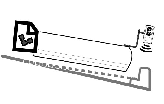
For machines with automatic controls, you can control the height of both blade tips in the following way:
- The automatic controls adjust the height of one blade tip using the sonic tracer to maintain a preset elevation above a reference surface, such as a curb.
- The automatic controls adjust the height of the other blade tip to maintain the 3D design elevation or slope.
To select a guidance combination:
- From the Dashboard, tap the Machine Setup tile.
- From the Machine Setup screen, select a 3D positioning source such as Dual GNSS.
- From the Guidance Combination field, tap the Open icon
 . The Guidance Combination screen displays.
 - The guidance combinations that are currently installed on your machine are listed. Select one of the sonic tracer combinations, for example, Sonic + 3D Elevation and tap Apply.
- You are returned to the Machine Setup screen. Tap Apply.
- From the Dashboard, tap the Job Setup tile.
- From the Job Setup screen, select either Design or Infield as the Mode and then select the design to receive guidance to. Tap Apply.
- From the Dashboard, tap Start to enter the work screen.
TIP – For quick access to the Guidance Combination screen, touch and hold the guidance combination icon in the guidance bar, at the top of the work screen. Alternatively, a single tap will cycle through the Quick Change list in the Guidance Combination screen. For less used combinations, use the re‑order list icon  to drag and drop them into the Other Available combination list.
Bench sonic tracer
Prepare to bench
To prepare to bench a sonic tracer:
- If required, adjust the pitch and roll of the blade, so that the blade is in its working position.
- If you are using 3D Elevation or 3D Slope on the opposite end of the blade, enable Autos and allow the cutting edge to drive to the target design. Alternatively, manually drive the cutting edge to the target design.
-
Get out of the cab and position the sonic tracer over the reference surface (for example, a curb) or stringline by adjusting the L‑shaped support tube. Adjust the support tube so that:
- The sonic tracer is between 400 mm (16 inches) and 1 m (40 inches) horizontally from the blade tip
- The tube is perpendicular to the machine wheelbase
- If applicable, the sonic tracer is centered directly over the stringline
-
Adjust the sonic tracer on the support tube so that its distance above the reference surface is one of the following:
- Between 200 mm and 1300 mm (8 inches and 51 inches) for a curb or design surface
-
Between 200 mm and 900 mm (8 inches and 36 inches) for a stringline
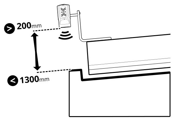
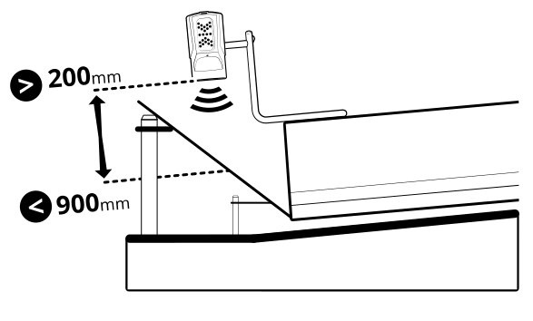
TIP – The greater the distance between the sonic tracer and the reference surface, the larger the sonic tracer’s operating radius is. It is best practice to have the sonic tracer about 800 mm (31.5 inches) above a curb or about 450 mm (18 inches) above a stringline.
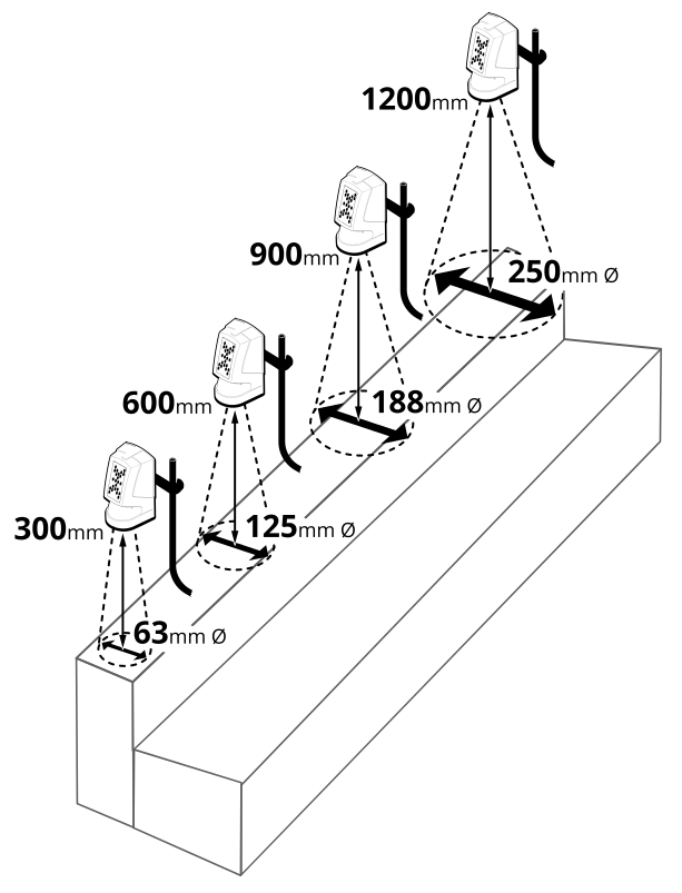
- Adjust the sonic tracer in its mount so that it is approximately vertical.
- Get back in to the cab.
-
To bench, use either of the methods described in the following table:
Bench method Description Bench with a relative elevation Place the sonic tracer controlled blade tip as described above.
This sets Cut/Fill to 0.00 at that position and you can enter an offset above or below the benched height to get guidance to.
Bench with a reference elevation (known elevation) Place the sonic tracer controlled blade tip on a benchmark with a known elevation.
This sets Cut/Fill to 0.00 at that position and you can then enter a known elevation to get guidance to (instead of an offset away from the benched position).
TIP – If you change the pitch and/or roll of the blade after you’ve benched you must re‑bench to maintain accurate guidance.
Bench with a relative elevation
Use this method if you wish to set 0.00 Cut/Fill at the current blade tip position and then work away from this using elevation offsets and the inc/dec switches. For example, you may have a plan set that gives offset distances between reference surfaces.
- Tap the Bench Sonic Tracer icon
 in the shortcut bar to bench directly or touch and hold the icon to open the Bench Sonic Tracer screen. Alternatively, access the Bench Sonic Tracer screen via the Work Settings menu.
 - Ensure the Reference Elevation toggle is off.
- If required, toggle Clear Offset on Bench off to keep your previous elevation offset after benching. The system remembers your selection for future use.
- Position the blade as described above in Prepare to bench.
- Tap Bench.
NOTE – Once a sonic tracer is benched, it must be operated within ± 70 mm (2.8 inches) of the benched elevation. This region is known as the sonic gate. This is useful if there is a gap in the stringline or curb, when the sonic tracer goes over the gap Autos will be suspended. When the sonic tracer picks up the stringline or curb again Autos will re‑engage (provided this happens within the 60 second timeout period).
Bench with a reference elevation (known elevation)
Use this method if you wish to enter a target elevation value to drive the blade to. For example, you may have a plan set where finished floor heights are given as elevations.
NOTE – Benching a sonic tracer with a reference elevation is only practical if the stringline, curb or surface the sonic is tracing to is level, with no elevation change along it.
- Tap the Bench Sonic Tracer icon
 in the shortcut bar to bench directly or touch and hold the icon to open the Bench Sonic Tracer screen. Alternatively, access the Bench Sonic Tracer screen via the Work Settings menu.
 - If required, toggle Clear Offset on Bench off to keep your previous elevation offset after benching. The system remembers your selection for future use.
-
Toggle the Reference Elevation on and enter the value. The reference elevation is calculated as follows:
- If you are benching with the blade tip on the design surface or at the elevation to which you want guidance, the reference elevation is as specified on the plan set or surveyed stake.
-
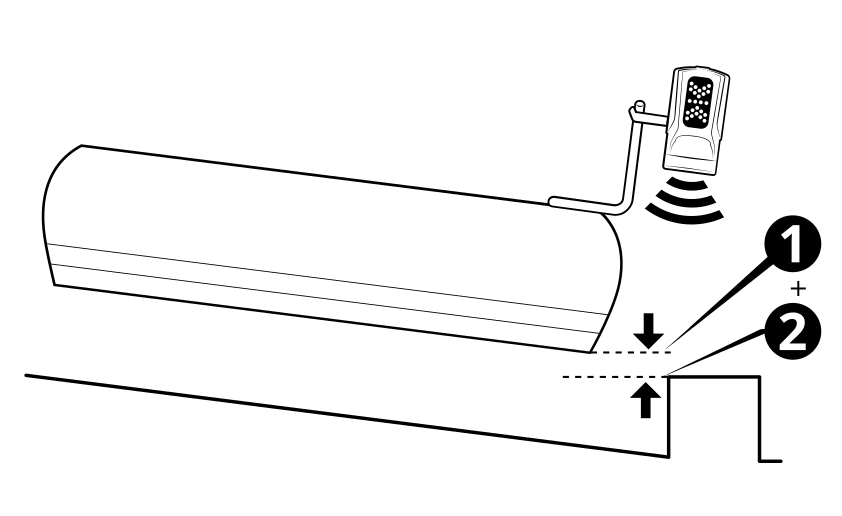
If you are benching over a known reference elevation such as a stringline or curb, add the vertical distance from the blade tip 1 to the known reference elevation 2 . If the blade tip is below the reference elevation then 1–2. For example, if the curb has a known elevation of 103.258 m (338.77 ft) and the blade tip is 0.100 m (0.33 ft) above the top of the curb, enter 103.358 m (339.10 ft) as the reference elevation value.
- Tap Bench.
- Open the Elevation Offset screen from the Work Settings menu or you can touch and hold the elevation offset icon in the guidance bar. Enter the Elevation you want the blade to drive to.
NOTE – Once a sonic tracer is benched, it must be operated within ± 70 mm (2.8 inches) of the benched elevation. This region is known as the sonic gate. This is useful if there is a gap in the stringline or curb, when the sonic tracer goes over the gap Autos will be suspended. When the sonic tracer picks up the stringline or curb again Autos will re‑engage (provided this happens within the 60 second timeout period).
Setting offsets
Set a sonic offset
If required you can use an elevation offset for the sonic tracer controlled blade tip. This enables you to create surfaces that are achievable in a single pass.
You can access the Left/Right Sonic Offset screen from the Work Settings menu . Or, you can touch and hold the sonic offset icon in the guidance bar. Enter the offset of the sonic tracer from the benched elevation and tap Apply.
Set a horizontal offset
If required you can set a horizontal offset to a line. This is useful when you are using sideshift Autos and the blade tip is not within sideshift range.
You can access the Horizontal Guidance screen from the Work Settings menu. Or, you can touch and hold the horizontal offset icon in the guidance bar. Tap Select Line to select the horizontal line and then once back in the Horizontal Guidance screen, enter the offset and tap Apply.
Set an elevation offset
If required you can set an elevation offset for the 3D Elevation or 3D Slope controlled blade tip.
You can access the Elevation Offset screen from the Work Settings menu. Or, you can touch and hold the elevation offset icon in the guidance bar. For more information see Using Elevation Offsets.
Useful text items
When you use a sonic tracer for guidance the following text item can be helpful: Sonic Distance Left/Right.
Troubleshooting
The LED display of a sonic tracer indicates some of the common error conditions.
| LED pattern | Meaning |
|---|---|
| Down arrows flashing alternately. |
Above the sonic gate. Lower the sonic tracer so that it is within ± 70 mm (2.8 inches) of the benched elevation. |
| Up arrows flashing alternately. |
Below the sonic gate. Raise the sonic tracer so that it is within ± 70 mm (2.8 inches) of the benched elevation. |
| Outer up and down arrows flashing alternately. | No echo detected. The sonic tracer may not be benched or is too far above the reference surface to receive a return signal. |
