Best Practices When Using Autos on Cat D6 machines
NOTE – For all other machine models, seeBest Practices when Using Autos.
TIP – For optimum performance when using Autos features, avoid connecting the Operator App device to the system via Wi-Fi. Ensure that you use a wired connection.
For the best results when using Autos, follow the practices outlined below.
WARNING – The bowl may move without warning when Autos is engaged. These sudden movements could cause injury to anyone near the bowl, or damage to an unattended machine. Always put the system in Manual, lock out the hydraulics and engage the machine's park brake before you leave the machine, or when somebody is working near the bowl.
Prepare the machine
Before you use Autos, you should check that:
- The machine is in good operating condition.
- None of the cylinder connection points have excessive wear. If the cylinder connection points are loose it can cause movement in the blade and will affect the accuracy of the system.
- The pivot bearings are well lubricated and do not have excessive wear. If the pivot bearings are loose it can cause movement in the blade and will affect the accuracy of the system.
- The track tension is within manufacturer's specification, adjust as needed. If the track tension is too loose or too tight it will affect the performance of Autos.
- The measure‑up and calibration of the machine is accurate. The surface you build cannot be better than the accuracy of these measurements and calibrations.
- A valve calibration has been performed.
Best practices for operating dozers
Autos can be used in a variety of applications to increase productivity, from bulk earthmoving to finish grading.
Procedures to perform every time you use Autos
-
Make sure the machine’s hydraulic oil is at its normal operating temperature.
-
Turn the throttle up to maximum revs.
The hydraulic pump should always have maximum power available to it, so the hydraulic system can respond to automatic commands as quickly as possible.
-
Position the blade within the control range.
TIP – Use the lightbars, cut/fills and buzzer to assist you to position the blade within the control range. The Control Range is also available as a text item.
- Control the speed of the dozer through the gears. If your dozer has a setting that allows full engine speed even through de–acceleration then turn it on. This will give best performance when building the start pad and during the initial acceleration into the run.
- Due to the harmonics of undercarriage every dozer has a certain speed that produces optimal performance. Vary ground speed often to find this speed. Use this speed when making final passes.
Procedures to perform, as required
-
Update the cutting edge length to account for the wear of the blade. If required, update the values in the Cutting Edge Length screen, accessed via the Edit button on the Blade Manager screen.
NOTE – The frequency at which you need to check the cutting edge length depends on factors such as the type of material you work with and the durability of the cutting edge.
-
Replace the cutting edge if there is more than a 3 mm (⅛ inch) deviation.
The blade wear deviation can occur in different ways; it can arc from the center to the edges creating a downward bow, it can arch from the edges to the center creating an upward bow or from the center wearing at either end.
To check the deviation, do one of the following:
- Place the cutting edge on or slightly above a flat surface, such as concrete or pavement.
- Tie a string across the bottom of the cutting edge.
Compare the cutting edge to the surface or string. In each case, the straight edge of the blade should have less than 3 mm (⅛ inch) deviation. If the cutting edge does not meet this specification, replace it.
-
Ask your technician to perform a new valve calibration when:
- The ambient temperature is much lower or higher than when the last valve calibration was performed.
- The hydraulic system has been serviced or modified.
-
Check for machine wear points over time, and correct:
- Track slop. Track bounce can degrade the performance of Autos.
- Wear on the hydraulic ram connections. Check the lift ram and tilt ram connections.
- Ensure that very small hydraulic movements equals very small blade movements. If they do not, suspect wear in the hydraulic ram connections.
Operating practices that can improve performance
- To improve grading performance avoid using poor technique. Examples include:
- Operating too fast for the task being carried out and the material being worked.
- Cutting a rough surface at too high a speed. This can result in a rippled or wavy final surface.
- Moving too much material. This can cause the machine to rock forward and overcut.
-
Create a smooth starting pad.
The starting platform for your run is one of the most important things to get correct.
Spend time building this and use Autos to assist you. Crawling backwards and forwards at a very low speed will allow the blade to stay accurately on grade. Back-blading can help keep the pad smooth.
-
Use smooth acceleration.
When starting off from the pad, accelerate smoothly to grading speed. Make sure you pick up the material in the blade smoothly. Do not slam into a pile of gravel.
Any disturbance at the start of the run will cause the dozer to oscillate and build several waves in the surface before it recovers.
-
Use the correct blade load.
An empty blade is as bad as an overloaded blade. Keep the blade load to between one–quarter to one–half full.
With too much material in the blade, response is reduced as the blade must react against the material. Also it will spill out the sides and make general operation more difficult.
An empty blade is also bad as there is no dampening of the blade by the material. An empty blade is more likely to chatter or move up and down quickly.
Keeping one–quarter to one–half a blade load during the run will ensure that you can achieve optimum performance.
-
Autos optimization.
You can improve the performance of Autos by adjusting the values in the Autos Optimization screen. For example, if the finished surface shows short choppy waves, decrease the raise/lower speed.
Another example of when you might need to adjust the Autos optimization values is when material conditions change:
- Type
- Density
-
Moisture content
NOTE – For more information, see the Autos Optimization guide.
-
Use the correct blade angle.
On machines with a rotating blade, a small amount of angle will improve the smoothness of the surface over a square blade. Move the tip of the blade back at least 150 mm (6 inches) to increase the stability of the dozer. More angle is better but will depend on how the material must be moved.
The job will largely dictate where material is moved from and to, and angle on the blade will side-cast the material into a windrow.
Take a final pass of 10 mm (½ inch) to cut it down to the final height using an angled blade, if possible.
-
Making corrections.
If things go wrong, stop and back-blade, if required, to carry the blade load back. Back up a few more meters, and start again.
Operating practices when using Autos in conjunction with AutoCarry on Cat machines
On newer Cat machines, the AutoCarry feature and Autos (Grade Control) share the same Autos button on the joystick. If AutoCarry has been enabled in the integrated Cat machine display, pressing the auto switch on the joystick will engage or disengage both AutoCarry and Autos (Grade Control). The feature with the largest raise command or the smallest lower command takes control of the blade, with the exception that Autos (Grade Control) will not allow the blade to cut below design without a deliberate manual joystick command to over‑ride Autos.
There are times during the dozer work cycle when you need to be aware of which system will have control of the blade and when it would be beneficial to over‑ride or turn Autos off. This differs between the Snap to Grade and Latch to Grade auto modes.
The dozer cycle can be split into the following phases; Cut, Carry, Fill/Stack and Return. Each of these phases are discussed in the following sections.
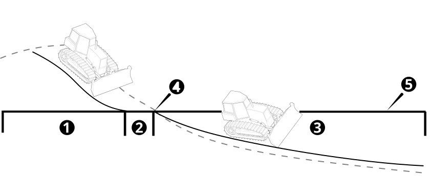
| 1 | Cut phase | 2 | Carry phase | 3 | Fill phase |
| 4 | Breakthrough point | 5 | Design |
Latch to Grade
Latch to Grade is available on newer Cat machines. For information on how to enable Latch to Grade, see the Autos Setup guide.
The following table provides an overview of when to over‑ride Autos, or turn Autos on and off during the dozer work cycle.
| Dozer cycle phase | Autos On/Off/Over‑ride |
|---|---|
| Cut | On |
| Carry | On |
| Breakthrough point | Temporarily over‑ride Autos with joystick |
| Fill | On, AutoCarry will manage blade load |
| Return | Off at the breakthrough point |
Cut phase
Turn Autos on as you load the blade with manual joystick commands, if a blade tip touches design then Autos will latch on. The latch will be broken if AutoCarry has the largest raise command and raises the blade to maintain forward drive; or if you make a deliberate joystick command (return the joystick to the neutral center position and then make a manual joystick raise or lower command).
Carry phase
Keep Autos on, AutoCarry will have control raising and lowering to achieve the target load factor unless a blade tip touches design. If a blade tip touches design then Autos will latch on.
NOTE – If AutoCarry tries to lower the blade causing a tip to touch design, Autos will take control and prevent the blade from cutting below design.
Breakthrough point and fill phase
You will need to visually monitor when the machine reaches the breakthrough point and transitions from the carry phase into the fill phase (where the existing ground slopes down away from design). As you reach this point and a blade tip touches design, Autos will latch on. To prevent this, you must temporarily over‑ride Autos with the joystick (return the joystick to the neutral center position and then use manual lower commands until the blade tip is below the design) to continue carrying the load down below design into the fill area.
AutoCarry is active and will continue to control the blade to achieve the target load factor while the load is carried down into the fill.
NOTE – When you start to spread the load you can raise the blade using the joystick - there is no need to turn Autos off with the auto switch.
NOTE – If you turn off Autos then AutoCarry will also turn off.
Return phase
Turn off Autos as you go into the return phase to prevent Autos latching to grade from below as the machine travels back through the breakthrough point.
Snap to Grade
Snap to Grade is available on newer Cat machines. For information on how to enable Snap to grade, see the Autos Setup guide.
NOTE – The Auto Control Range Limit timer which disables Autos after 1 minute while AutoCarry has control is not active.
TIP – Configure the Controls Range Limit text item to appear on the Text Ribbon on the Grade Control display.
The following table provides an overview of when to over‑ride Autos, or turn Autos on and off during the dozer work cycle.
| Dozer cycle phase | Autos On/Off/Over‑ride |
|---|---|
| Cut |
Off first, to load the blade. On, once enough load is acquired or as the blade gets close to design. |
| Carry | On. |
| Breakthrough point | On, over‑ride Autos with joystick until you are below design and the Auto Control Range Limit warning is triggered (orange banner on the display). |
| Fill | On. |
| Return | Off at the breakthrough point. |
Cut phase
Load the blade in the Manual control state. This is to prevent Snap to Grade driving the blade down to design when the blade tips enter the control range. This could cause track slip and AutoCarry to raise the blade, which could result in a hollow in the floor at the transition from cut to carry.
Turn Autos on when either the blade has acquired enough load or the blade is getting close to design.
Carry phase
Keep Autos on, AutoCarry will have control raising and lowering to achieve the target load factor unless both blade tips enter the control range, then Autos will snap to grade.
NOTE – If AutoCarry tries to lower the blade causing a tip to touch design, Autos will take control and prevent the blade from cutting below design.
Breakthrough point and fill phase
You will need to visually monitor when the machine reaches the breakthrough point and goes from the carry phase into the fill phase where the existing ground slopes down away from design. As you reach this point, the blade tips will enter the auto control range and will snap to grade (raise the blade back to design). You must temporarily over‑ride Autos with the joystick (hold it forward and use manual lower commands until the blade tip is below the auto control range limit and the orange warning banner displays on the display) to breakthrough the design and continue carrying the load down into the fill area. AutoCarry will manage the blade load into the fill.
NOTE – If you misjudge and stop over‑riding while still in the auto control range limit, then Autos will raise the blade back to design and the load will be lost.
NOTE – If you turn off Autos then AutoCarry will also be off.
Return phase
Turn off Autos as you go into the return phase to prevent Autos snapping to grade from below as the machine travels back through the breakthrough point.
Best practices for GNSS Precision Tolerance
Autos is available when GNSS precision is within the set tolerance limits for Fine, Medium, or Coarse modes. A technician can adjust these limits in the Web Interface. The table below explains when to use each mode and the corresponding Autos tolerance limits.
| Mode | Use when doing... | Default precision tolerance | Tolerance limit for Guidance | Tolerance limit for Autos |
|---|---|---|---|---|
| Fine | Finish grading | 0.030 m (1.181 inches) | 0.048 m (1.889 inches) | 0.001 - 0.048 m (0.039 - 1.889 inches) |
| The Fine tolerance limit must be less than the tolerance limit used for Medium. | ||||
| Medium | General work | < 0.045 m (1.771 inches) | 0.049 m (1.929 inches) | 0.002 - 0.049 m (0.078 - 1.929 inches) |
| Coarse | Work in areas with limited GNSS guidance | 0.100 m (3.937 inches) | 10.0 m (32.808 feet) | 0.050 - 0.100 m (1.968 inches - 3.937 inches) |
