Using Depth and Slope Mode
Depth and Slope mode lets you use slopes, sections, and offsets as required, to define your target grade.
You can also show the linework from a design file and get horizontal guidance to it, if your positioning source supports it and you have a license for 3D guidance. See Showing and guiding to linework.
NOTE – These instructions apply to both blade slope and cross slope systems. Use these instructions for either system configuration:
- Blade slope systems measure - blade slope only
- Cross slope systems measure - blade slope, blade rotation and machine mainfall
To select Depth and Slope mode:
-
From the Dashboard, tap the Machine Setup tile and select the positioning source that you require.
NOTE – The positioning source you select will determine the modes that you can select from the Job Setup screen.
- From the Dashboard, tap the Job Setup tile.
-
From the Job Setup screen select a project and set the Mode field to Depth and Slope.
- Optionally, if you have a 3D positioning source, select a design from the Design field to show linework.
- Tap Apply.
- From the Dashboard, tap Start. The work screen displays.
The work screen
In Depth and Slope mode, this icon displays at the top left-hand side of the work screen: 
Touch and hold the icon to open the Job Setup screen.
The Depth and Slope target icons
The target icons always appear in the same order left to right on the guidance bar, as shown below:
| Mainfall | Cross Slope | Horizontal Offset | Elevation Offset |
|---|---|---|---|
|
|

|

|

|

Use the target icons in the following ways:
- Tap to cycle through the configured target memories.
- Touch and hold to access the respective target configuration screens.
The target settings screens
NOTE – The Apply button saves values temporarily. The values are overwritten the next time you enter a different value. If you want to save the entered values as a memory, use the Save button.
- Use the Target Mainfall and Target Cross Slope screens to select, edit or create a new slope.
- If you save a section, use a unique name. You can use the saved section in either the mainfall or the cross slope orientation.
- Use the Elevation Offset screen to select, edit or create a new target offset.
- You can use the increment/decrement elevation offset switch to increase and decrease the offset.
NOTE – If you switch from Depth and Slope mode to Design mode, the system reverts back to Horizontal and Elevation Offsets of 0.00.
Showing and guiding to linework
If you have a 3D guidance solution and a license for 3D guidance, you can load a design containing linework in Depth and Slope mode. You can show the linework as a reference and select one of the lines for horizontal guidance:
-
Bench the machine in the work screen.
-
Either:
-
Touch and hold on the line to open the context menu and then select the guidance line.
-
Touch and hold this icon
to open the Horizontal Guidance screen and then select the guidance line.
-
Overlays
The overlays icon is in the top right-hand corner of the guidance bar: 
Use this icon to directly access the Overlays screen, which controls what displays on the guidance view.
The guidance view
The guidance view displays the machine relative to the surface being worked. You can set up to three different views to display at once, from the following view types:
-
3D
NOTE – The 3D view only renders the design surface for a radius of 150 m (about 500 feet) from the current machine position.
- Cross Section
- Profile
- Plan
- Cut/Fill Left
- Cut/Fill Right
- Cut/Fill Center
Text items
Use the text ribbon area (across the bottom of the guidance view) to display text items of your choice. By default, the system displays ribbon items appropriate for your machine. Useful text items for Depth and Slope mode are:
- Cut/Fill Left and Cut/Fill Right
- Body Slope
- Body Mainfall
Touch and hold any text item in the text ribbon to open the corresponding context menu:
-
Tap Add
 to select a new text item to add to the text ribbon.
 -
Tap Replace
 to select another text item to replace the current one.
 -
Tap Remove
 to remove the current text item from the text ribbon.
At the bottom of the context menu, you can tap Go to Text Ribbon  . Alternatively you can access it from the System Settings menu
  . The Text Ribbon screen allows you to:
-
Drag-and-drop items to reorder your list. Alternatively, you can drag a text item in the text ribbon to shuffle it.
-
Tap Edit to select which items appear.
-
Tap Default to reload the default ribbon items for your machine.
-
Enable or disable the display of the text ribbon in the work screen.
System settings
The System Settings icon is on the work screen:
Use System Settings to access and configure various functions, including (but not limited to):
- Lightbars
- Units
- File Transfer
- Increments (where the inc/dec switches step size can be set)
The shortcut bar
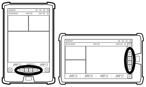
The shortcut bar enables you to easily perform frequently repeated tasks. The shortcut icons are for Depth and Slope relevant items such as Blade Focus.
If a shortcut icon is blue, then you must configure that function before the system provides guidance for your machine. This includes:
- Bench Heading
 which sets the direction of the design slope (mainfall).
 - Bench Elevation which you can use to set a relative
 or absolute
  reference elevation.
Tap the blue icon to bench your machine or touch and hold the icon to open the relevant settings screen and then edit as required.
The Back icon
The Back icon is in the top left‑hand side of the title bar: 
You can tap the icon or title to return to the previous screen; either the Dashboard or work screen.
Work settings
The Work Settings icon is in the lower right-hand side of the work screen: 
Use the Work Settings menu to access and configure those settings that change according to the requirements of each individual task, including (but not limited to):
- Target Mainfall
- Target Cross Slope
- Blade
For more information
See these guides in the overflow menu:
- Bench Heading
- Bench Elevation
