Mapping
NOTE – Mapping and the features mapping offers are configurable in the Web Interface by your technician. In addition, advanced mapping features may only be available if the correct license is installed. If mapping or a mapping feature is not available on your system, contact your technician or dealer.
Mapping data is the cutting edge or track elevation, recorded as the machine works.
You can also optionally:
- Display the cut/fill differences between the recorded map data and the guidance surface.
-
Display an initial map generated from the cut/fill differences between a pre-mapped surface, called a ground surface, and the guidance surface.
For example, if the ground surface is based on a survey of the original site, then the initial map could enable you to move dirt around the site more efficiently.
NOTE – The ability to select a ground surface is a licensed feature. Contact your dealer for more information.
Using mapping
Mapping is available when you have an office design or infield surface loaded.
The shortcut key
When you are in the work screen, you can use the shortcut key  to turn the display of cut/fill mapping data on and off.
You can also touch and hold the shortcut key to open the Cut/Fill Mapping screen.
Mapping rules
Active Body IMU systems
Mapping data is collected when the following conditions are met:
-
When the cutting edge is within 100 mm (4 inches) of the track plane, blade mapping of the cutting edge starts. Blade mapping continues as long as the cutting edge remains within 150 mm (6 inches) of the track plane.
NOTE – 100 mm (4 inch) and 150 mm (6 inches) are the default values for starting and continuing mapping. These values may be changed by your technician.
OR
- Map data is calculated using the elevation of the tracks (track mapping).
Track Mapping - Active Body IMU systems only
When track mapping is enabled in the Web Interface, cut/fill mapping for the tracks displays on the work screen. You can use track mapping to map the cut/fill of an area by driving the machine over the area with the blade raised over 100 mm (4 inches) above the track plane.
When track mapping is enabled and the cutting edge is within 100 mm (4 inches) of the track plane, both track mapping and blade mapping display on the work screen. Track mapping may appear as a different cut/fill to the blade cut/fill.
Inactive Body IMU systems
Mapping data is collected when the following conditions are met:
-
When Autos is engaged.
OR
-
If the cutting edge of the blade is within 100 mm (4 inches) of the target surface, then mapping starts and map data is calculated using the elevation of the blade (blade mapping). Mapping continues as long as the cutting edge remains within 150 mm (6 inches) of the target surface.
NOTE – 100 mm (4 inch) and 150 mm (6 inches) are the default values for starting and continuing mapping. These values may be changed by your technician.
NOTE – Your technician can select whether blade mapping occurs when the machine is moving in any direction, or only when the machine is moving forward.
Start mapping with an empty map
To start mapping with an empty map:
- From the Work Settings menu open the Cut/Fill Mapping screen, or touch and hold in the shortcut bar.
- Optionally, toggle Display Mapping Data on or off.
- If available, from the Ground Surface drop down, select None.
- Tap Apply.
NOTE – Changing the Ground Surface setting deletes any existing mapping data stored on the machine.
Start mapping with a pre-mapped surface
NOTE – The ability to select a ground surface is a licensed feature. Contact your dealer for more information.
To start mapping with a pre-mapped surface:
-
Transfer a ground surface .ttm file onto the machine. Either sync with Connected Community or import the ground surface file from a USB flash drive.
NOTE – If a Connected Community sync adds a new ground surface .ttm file to the current project, then a notification is displayed.
NOTE – To import a ground surface .ttm file from a USB flash drive, the ground surface file must be in the ProjectLibrary \ Projects \ [project name] \ OfficeData folder on your USB flash drive.
- From the Work Settings menu open the Cut/Fill Mapping screen, or touch and hold in the shortcut bar.
- Optionally, toggle Display Mapping Data on or off.
- From the Ground Surface drop down, select the ground surface file to load.
-
Tap Apply. If Display Mapping Data is on, a cut/fill map is generated showing the difference between:
- The guidance surface of the currently loaded design; and
- The ground surface
NOTE – If Lane Guidance is selected, then the cut/fill map generates using the lane guidance surface. In this case, cut/fill data is only displayed within 20 m (65 ft) of the machine.
NOTE – Changing the Ground Surface setting deletes any existing mapping data stored on the machine.
As you work, the pre-mapped ground surface elevations are overwritten by the measured elevations.
If you select a different design within the same project, the cut/fill map regenerates using the new design.
Downloading ground surface data from an online source
If your technician has enabled access, you can request the system to download the latest ground surface data in a .ttm file from an online source. This includes data from other machines on the site.
This option downloads data once when requested.
- On the Cut/Fill Mapping screen, set the Ground Surface field to WorksOS download.
- Tap Apply.
Downloading information for a large area can take a while.
NOTE – This feature requires an Advanced Mapping license. A machine can only download ground surface data for a compatible design.
Deleting map data
To delete any existing mapping data stored on the machine:
- From the Work Settings menu open the Cut/Fill Mapping screen, or touch and hold in the shortcut bar.
- Tap Reset Map.
If a pre-mapped surface was initially loaded and Display Mapping Data is on, then the cut/fill map of the differences between the design surface and the pre-mapped surface is reset to its original state.
Inspecting a map
To view details of the mapping data on a plan view, touch-and-hold on an onscreen location where mapping data is recorded. Select Inspect Map from the context menu.
The work screen
Work screen items that affect the recording and display of mapping information are described in the following sections.
The guidance bar
The target icons relevant to Mapping are shown below:
| Vertical elevation offset | Perpendicular elevation offset |
|---|---|

|

|
NOTE – Either the vertical elevation offset or perpendicular elevation offset icon displays, depending on which offset type is in use.
Use the offset icons in the following ways:
- Tap to cycle through the configured offset memories.
- Touch and hold to access the respective offset configuration screens.
The guidance view
The guidance view displays the machine relative to the surface being worked. You can set up to three different views to display mapping data at once:
- Cross-section
- Profile
- Plan
NOTE – Mapping data is not visible in the 3D view.
Mapping data is displayed in the following way:
| Color | Meaning |
|---|---|
| Shades of red |
The shaded area is above the working surface elevation (cut). |
| Shades of green | The shaded area is within on-grade tolerance of the working surface elevation (on-grade). |
| Shades of blue |
The shaded area is below the working surface elevation (fill). |
| Gray | Cut/fill values are being calculated and loaded. |
System Settings
The System Settings icon is in the lower left-hand side of the work screen: 
Use System Settings to access and configure various functions, including (but not limited to):
- Grade Tolerance
- File Transfer
The shortcut bar
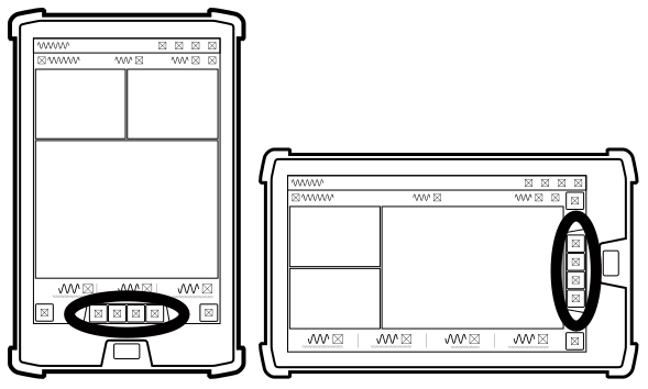
The shortcut bar enables you to easily perform frequently repeated tasks. The shortcut icon for mapping is:
To display or hide mapping data, tap the mapping icon in the shortcut bar.
To open the Cut/Fill Mapping settings screen, touch and hold the mapping icon.
Work Settings menu
The Work Settings icon is in the lower right-hand side of the work screen: 
Use the Work Settings menu to access and configure those settings that change according to the requirements of each individual task, including (but not limited to):
- Cut/Fill Mapping
- Elevation Offset
For more information
See these guides in the overflow menu:
- Transferring Files
- Using Elevation Offsets
Troubleshooting
The table below lists some of the error messages that may appear when you use mapping.
| Error Message | Possible cause(s) |
|---|---|
| Unable To Load Cut/Fill Map |
|
