Using Design Mode
Design mode lets you do any of the following:
-
Select and load a 3D design created in the office
-
Select and load, or create, a guidance surface
-
Start working without a design or surface
Designs may contain one or more surfaces.
Designs and infield or office surfaces may contain optional linework.
You can get guidance in Design mode in multiple ways:
| Guidance to... | For more information... |
|---|---|
|
Office Surface
|
Select a Project + Design file + Office Surface. See below. |
|
Infield Surface
|
You can create or select an infield surface. Select a Project + Infield Surface. If you load an office design as well, you can show up to 2 surfaces from the design as reference surfaces. See the Infield Surfaces guide. |
|
3D Line
|
Select one of the following:
When you select a 3D line for guidance (on the work screen), the system generates a temporary guidance surface for it. See the 3D Lines guide. |
|
2D Line
|
Select one of the following:
When you select a 2D line for guidance, the line’s elevation matches the surface. See the Horizontal Guidance guide. |


For information on design file formats, see Project and Design Files.
Selecting Design mode
- From the Dashboard, tap the Machine Setup tile.
-
From the Machine Setup screen, select the 3D positioning source that you require and tap Apply.
NOTE – The positioning source you select will determine the modes that you can select from the Job Setup screen.
- From the Dashboard, tap the Job Setup tile.
- From the Job Setup screen, select or create a project from the Project field.
- Set the Mode field to Design.
- Select any of the following as required:
- One or two design files, see Selecting a cut design and a fill design - Design Swap
- A guidance surface, see Selecting a surface.
- A master alignment (if available in the design).
- From the Dashboard, tap Start. The work screen displays.
Selecting a cut design and a fill design - Design Swap
When working in Design mode, you can apply two different designs from the same project to use with Sequence Assist:
-
Design A (Cut) - select a design specifically for cutting, this design is used when the machine is in the Ready to Dig and Ready to Return stages
-
Design B (Fill) - select a design specifically for dumping, this design is used when the machine is in the Ready to Haul and Ready to Unload stages
The cut and fill designs automatically apply as the Sequence Assist stages are changed. If you want to manually change the design, tap  on the guidance bar.
If only one design is selected, the design is applied to both cut and fill and you must acknowledge a warning message that displays. On the work screen, the Design Swap shortcut will not display.
Selecting a surface
On the Job Setup screen, tap  beside the Guidance Surface field to open the Surfaces Manager screen.
It shows all the surfaces available for the current design and enables you to select surfaces. You can select one guidance surface and up to two reference surfaces at once. You cannot get guidance to a reference surface, and it will only display on the cross section and profile views.
The list of surfaces is sorted into office surfaces and infield surfaces. Tap the Office or Infield button to select which surfaces display first:
-
Office surfaces are contained in a design, so the office surfaces that are available differ depending on which design is selected.
-
Infield surfaces are contained in a project, so the infield surfaces that are available remain the same for all designs in a project, or if a design is not selected.
To select a surface:
-
Select the round button for the type of surface: Guidance or Reference.
-
Tap the surface to assign. If a surface is already selected, it is gray.
To deselect a surface, tap the  button beside the surface name.
If you tap a surface in the list when the available surfaces are already occupied:
-
Guidance surface: your selection will replace the existing guidance surface selection.
-
Reference surface: your selection will replace the second reference surface selection.
Tap the  button beside an infield surface to edit, rename, or delete it.
Touch and hold the icon to open the Job Setup screen.
Project and design icons
The system displays icons representing the selected guidance options on:
-
The work screen's guidance bar
-
The Job Setup screen's infobox
| Icon | Description |
|---|---|
|
|
|
|
|
|
|
|
|
|
|
|
|
|
|
|
|
|
|
|
|
|
|
|

|
|

|
Design - Cut |

|
Design - Fill |
The Design offset icons
The offset icons always appear in the same order left to right on the guidance bar, as shown below:
| Horizontal offset | Vertical elevation offset | Perpendicular elevation offset |
|---|---|---|

|

|

|
NOTE – Either the vertical elevation offset or perpendicular elevation offset icon displays, depending on which offset type is in use.
Use the offset icons in the following ways:
- Tap to cycle through the configured offset memories.
- Touch and hold to access the respective offset configuration screens.
The offset settings screens
NOTE – The Apply button saves values temporarily. The values are overwritten the next time you enter a different value. If you want to save the entered values as a memory, use the Save button.
- Use the horizontal offset screen to select a line and configure an offset value.
- Use the elevation offset screen to configure a vertical or perpendicular offset.
Overlays
The overlays icon is in the top right-hand corner of the guidance bar: 
Use this icon to directly access the Overlays screen, which controls what displays on the guidance view.
The guidance view
The guidance view displays the machine relative to the surface being worked. You can set up to three different views to display at once, from the following view types:
-
3D
NOTE – The 3D view only renders the design surface for a radius of 300 m (about 1000 feet) from the current machine position.
- Cross-section
- Profile
- Plan
- Cut/Fill Left
- Cut/Fill Right
- Cut/Fill Center
- Text Grid
Text items
Use the text ribbon (across the bottom of the guidance view) to display text items of your choice. By default, the system displays ribbon items appropriate for your machine. Useful text items for Design mode are:
- Offline
Touch and hold any text item in the text ribbon to open the corresponding context menu:
-
Tap Add
 to select a new text item to add to the text ribbon.
 -
Tap Replace
 to select another text item to replace the current one.
 -
Tap Remove
 to remove the current text item from the text ribbon.
At the bottom of the context menu, you can tap Go to Text Ribbon . Alternatively you can access it from the System Settings menu  . The Text Ribbon screen allows you to:
-
Drag-and-drop items to reorder your list. Alternatively, you can drag a text item in the text ribbon to shuffle it.
-
Tap Edit to select which items appear.
-
Tap Default to reload the default ribbon items for your machine.
-
Enable or disable the display of the text ribbon in the work screen.
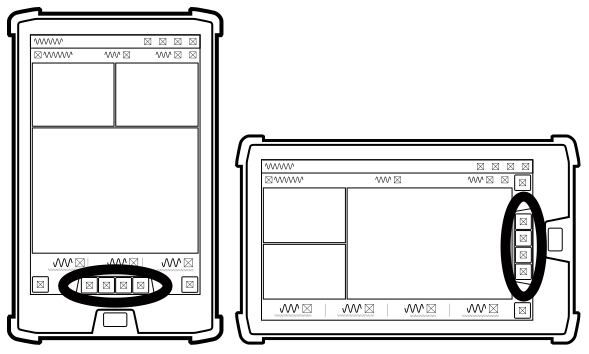
The shortcut bar
Work settings
The Work Settings icon is in the lower right-hand side of the work screen: 
Use the Work Settings menu to access and configure those settings that change according to the requirements of each individual task, including (but not limited to):
- Elevation Offset
- Record Point
For more information
See these guides in the overflow menu:
- Autos Setup
- Autos Optimization
- Best Practices when Using Autos
