Layout
You can use FieldLink to lay out points created with office software and transferred to the field. You can also lay out points you create in the field, or lay out lines by selecting points.
Lay Out Points
Points can be created within FieldLink or with office software such as Vico, Tekla, SketchUp, Trimble Business Center, Trimble Field Points for AutoCAD or Revit, or even other non-Trimble software. The points measured should be compared to the model to ensure any deviations, changes or issues are documented in the as-built model or drawings.
- Tap Measure
 and then tap Lay Out. The Point icon is automatically selected.
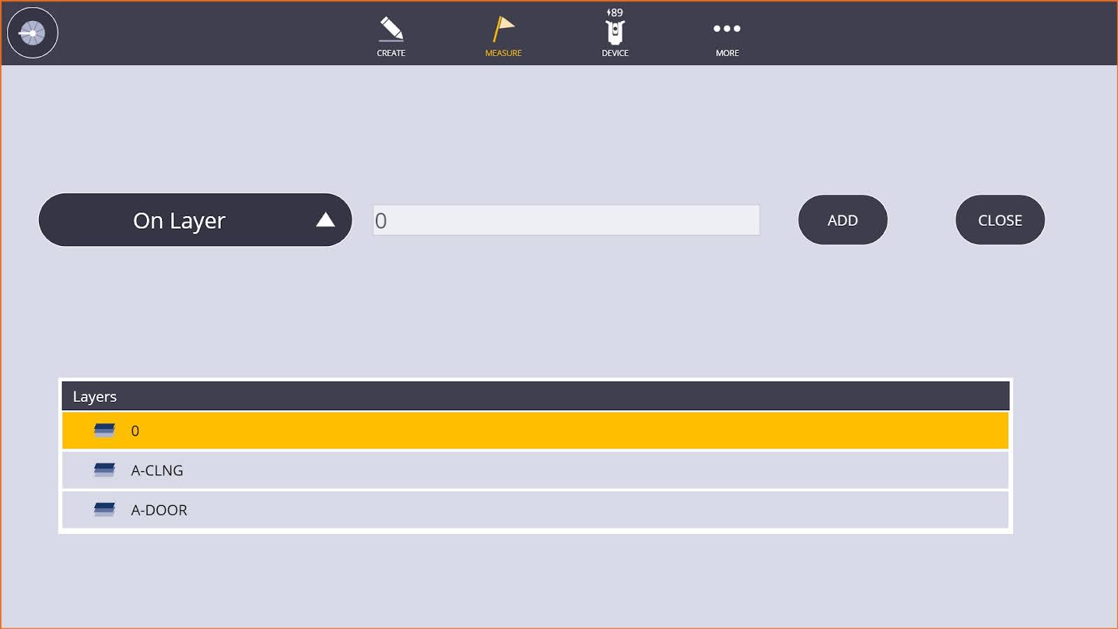
 - You can isolate points by selecting the appropriate layer under the Layer icon
 or by pressing the Point List icon
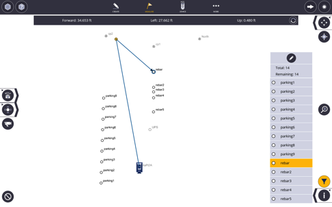
  in the lower left and using the Point Filter options to create a point list for your layout session.
 - Tap on the first point you need to lay out. If there are multiple points on top of one another or close together, a point selection box appears in the lower left corner and you can select the correct point.
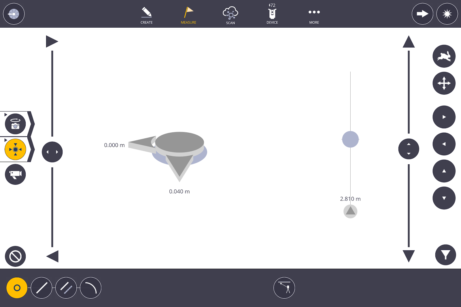
- The Direction Bar at the top indicates back or forward to the RTS, left or right as you are looking at the RTS, and up or down to the correct elevation. You can toggle the direction bar to give horizontal/vertical changes or the Back/Forward, Left/Right, Up/Down bar.
- You also now have the option to select the Corner Bullseye to display on the screen under Map Options. If you have a point list created, you can also look at point information including position, layer and attributes for each point.
- If you are in laser mode, the RTS automatically aims at the point as soon as you tap on the point. If using Visual Layout as checked in the Measurement Settings, the laser beam moves to the correct X, Y position and shows any vertical deviation in the lower dialogue bar.
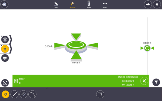
- Once you are within approximately 3’ (1 meter) from the point, the screen automatically changes to a bullseye mode. You can change back to the plan view by tapping the Bullseye icon.
- If the laser fails to measure after three attempts, but is very close, you have the option to maneuver the laser manually with the joystick features and or the nudge buttons.
- Tap the Next arrow icon to advance to the next point if you do not want to store the as-built information for future use and quality assurance.
- Tap the Shoot icon to collect the as-built information and store this information for future use and quality assurance.
- Tap the Next arrow icon to advance to the next or nearest point as selected in the Measure Settings.
- The lower message bar appears giving the staked point information. Points measured within the tolerance settings appear as green check marks. Points outside of tolerance settings appear as a red X.
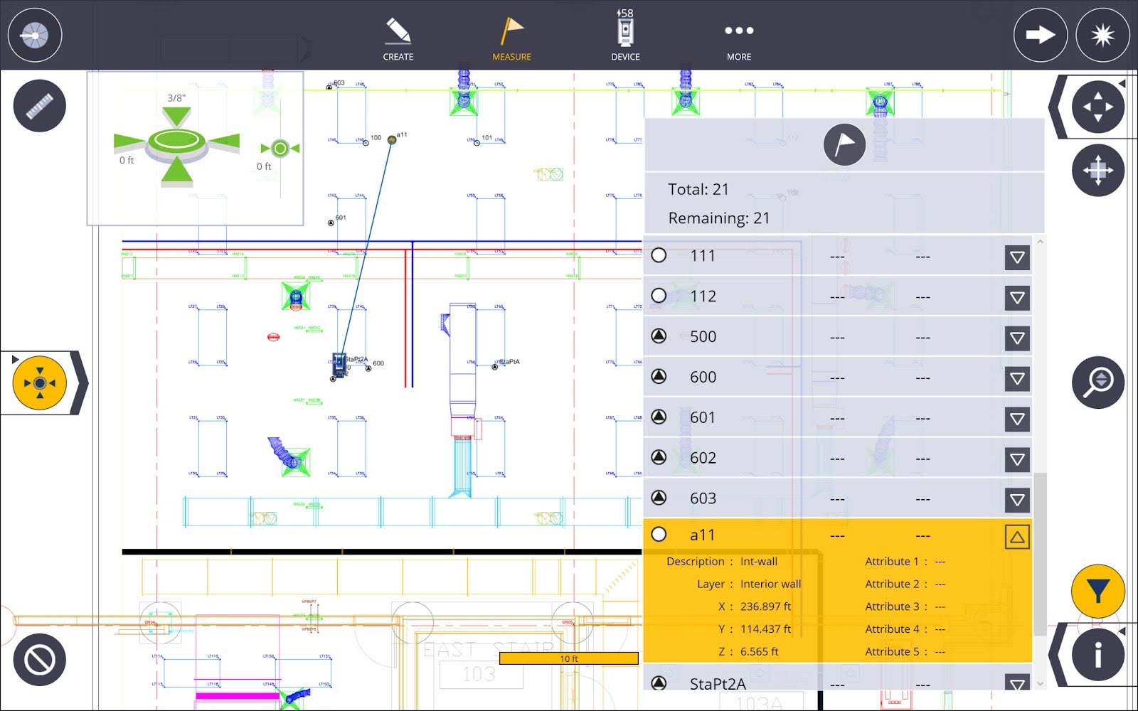
Point Layout List
If you have the 3D Feature Pack then you can generate a point layout list. The list can be populated by selecting individual points on the screen, multiple selections with a window or using a filter by name, description or layer.
NOTE – When using the functionality filter layer with points, only layers that include points are visible.
To create a point layout list:
- Tap the Point Layout List icon.
- Populate list via:
- Point selection on map
- Multiple selection with window selection
- Tap Add icon enter by Name, Description, or Layer
- To clear the list, tap the Cancel icon.
- To layout with list, tap the Layout icon.
- To advance to next in list, use Arrow.
Point Transfer
There may be times when you are unable to lay out on the floor because there are obstacles in the way. This feature allows you to switch between layout on the floor and the ceiling.
- Tap Measure and then tap Lay Out.
- Tap the Transfer icon
 at the lower part of the screen.
 - Follow the prompt to aim at either the floor or ceiling for a reference elevation. Then you can layout the point you want to transfer.
- You can then keep tapping on the Transfer icon to switch between floor and ceiling.
Lay Out Line
FieldLink provides the ability to layout linework by selecting 2 points to define a line segment or multiple points to define a polyline. Any temporary offset or interval points created in this section will not remain in the database until they are actually measured.
- Tap the Measure icon and then tap Lay Out.
- Tap the Line icon at the lower left of the screen.
- Tap the Clear Selection icon to select new points.
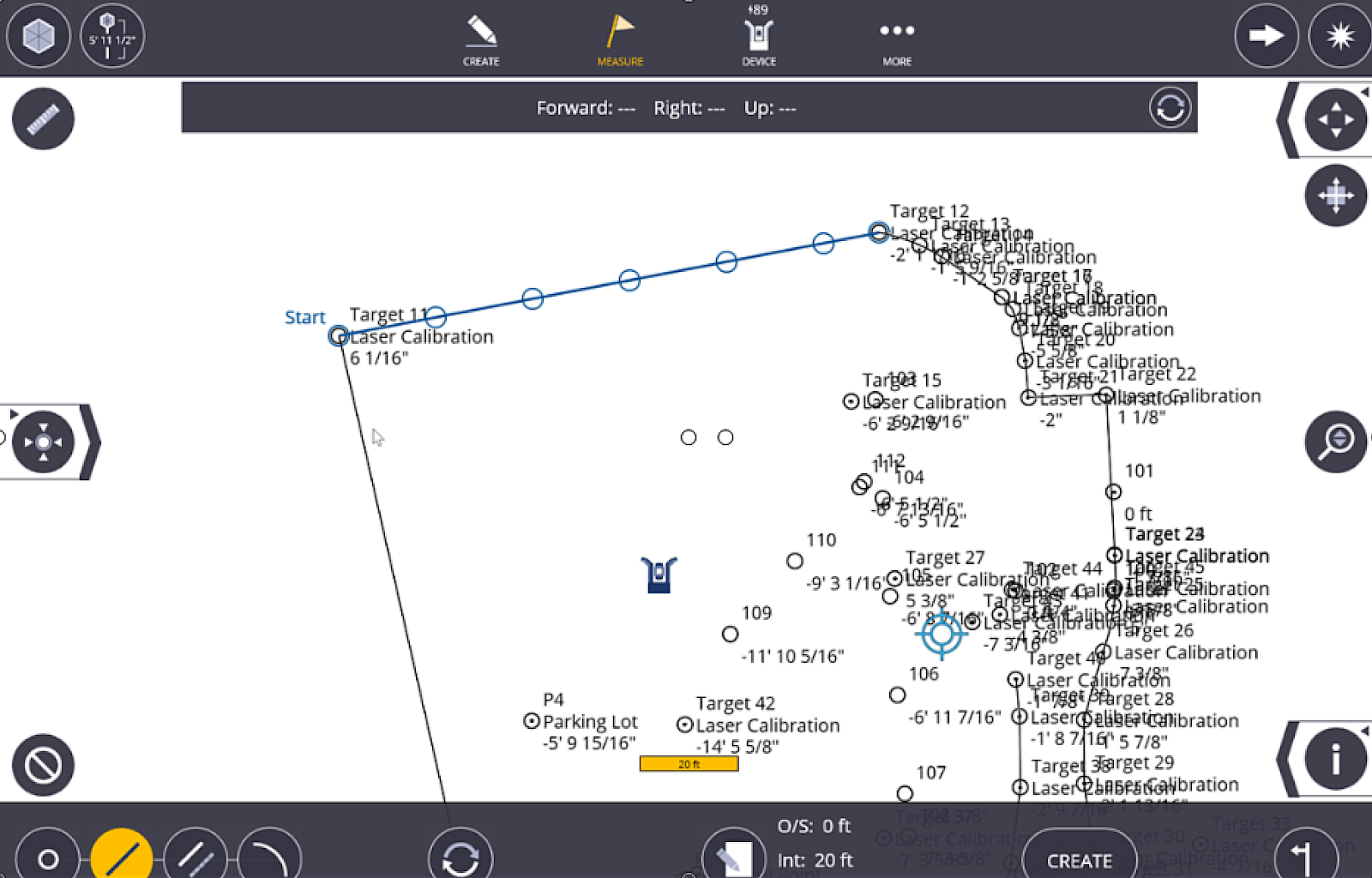
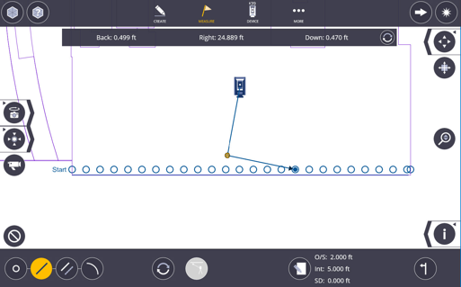
- Tap on two points to create the blue line to be staked. You can tap on additional points to offset a polyline around a building or utility run.
- Tap the Input Form
 to create an Offset Distance, Interval Distance, Start Distance, Name, Description and Layer of the points to be laid out along the line. You can enter “0” for the Interval Distance to take measurements along the line or offset line directly.
 - Tap the Input Form again to see the temporarily created points represented as open blue circles on the plan view to ensure the correct locations.
- Tap the Left/Right/Both Sides icon to toggle the offset points on either or both sides of the line.
- Tap on the first point to be measured if you entered an Interval Distance.
- The Direction Bar at the top indicates back or forward to the RTS, left or right as you are looking at the RTS, and up or down to the correct elevation. You can toggle the direction bar to give down and offset positions or the Back/Forward, Left/Right, Up/Down bar.
- If you are in laser mode, the RTS automatically aims at the point as soon as you tap on the point. If using Visual Layout, as checked in the Measure Settings, the laser beam moves to the correct X, Y position and shows any vertical deviation on the right-hand side of the screen.
- Once you are within approximately 3’ (1 meter) from the point, the screen automatically changes to a bullseye mode. You can change back to the plan view by tapping the Bullseye icon.
- Tap the Shoot icon to collect the as-built information and store this information for future use and quality assurance.
- Tap the Next arrow icon to advance to the next or nearest point as selected in the Measure Settings.
- The lower message bar appears giving the staked point information.
Lay Out to a Line
FieldLink provides the ability to layout linework and offset lines with Down and Out measurements by selecting only two points to define the line. This method is a quick and easy way to stake a continuous line anywhere on the line.
- Tap Measure and then tap Select Lay Out.
- Tap the Offset Line icon at the lower left of the screen.
- Tap the Clear Selection icon to select new points.
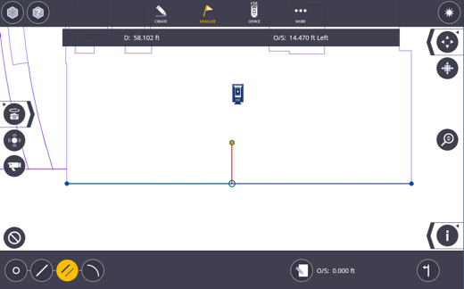
- Tap on two points to create the blue line to be staked.
- Tap the Input Form to create an Offset Distance, Name, Description and Layer of any points to be laid out along the line. You can enter “0” for the Offset Distance and take measures along the line directly.
- Tap the Input Form again to see the temporarily created line represented as a solid blue line on the plan view to ensure the correct location.
- Tap the Left/Right/Both Sides icon to toggle the offset line on either or both sides of the line.
- The Direction Bar at the top indicates down and offset positions. The down dimension is from the first point you selected to create the line, the offset distance is given as a right or left if you were standing at the first point you selected and are looking towards the line end point.
- Tap the Measure icon to collect the as-built information and store this information for future use and quality assurance.
- The lower message bar appears giving the staked point information. Points measured within the tolerance settings appear as green check marks. Points outside of tolerance settings appear as a red X.
Lay Out Arc
- Tap Measure and then select Lay Out.
- Tap the Arc icon at the lower left of the screen.
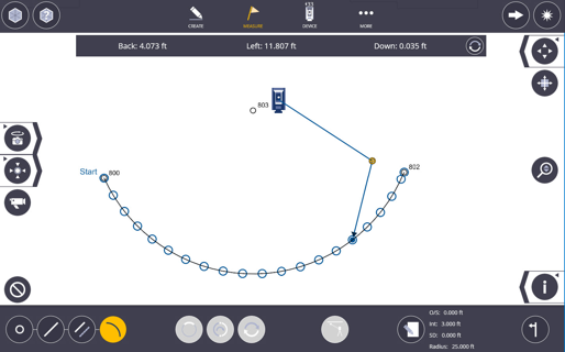
- Tap on two points to create the blue arc to be staked.
- To select new points, tap the Clear Selection icon.
- Tap the Input Form to create an Offset Distance, Interval Distance, Start Distance, Radius, Name, Description and Layer of any points to be laid out along the arc. You can enter “0” for the Interval Distance to take measures along the arc or offset arc directly.
- Tap the Input Form again to see the temporarily created arc represented as a solid blue line on the plan view to ensure the correct location.
- Tap on the Short Arc/Long Arc toggle icon to change the arc from the shortest distance along the arc to the longest distance along the arc.
- Tap on the Reverse Arc icon to change the direction of the arc.
- Tap the Left/Right/Both Sides icon to toggle the offset line on either or both sides of the line.
- If you entered an Interval Distance, tap on the first point to be measured.
- The Direction Bar at the top indicate back or forward to the RTS, left or right as you are looking at the RTS, and up or down to the correct elevation. You can toggle the direction bar to give down and offset positions or the Back/Forward, Left/Right, Up/Down bar.
- If you are in laser mode, the RTS automatically aims at the point as soon as you tap on the point. If using Visual Layout as checked in the Measurement Settings, the laser beam moves to the correct X, Y position and shows any vertical deviation on the right-hand side of the screen.
- Once you are within approximately 3’ (1 meter) from the point, the screen automatically changes to a bullseye mode. You can change back to the plan view by tapping the Bullseye icon.
- Tap the Shoot icon to collect the as-built information and store this information for future use and quality assurance.
- The lower message bar appears giving the staked point information. Points measured within the tolerance settings appear as green check marks. Points outside of tolerance settings appear as a red X.
- Tap the Next arrow icon to advance to the Next or Nearest point as selected in the Measure Settings.
3D Perspective Model View
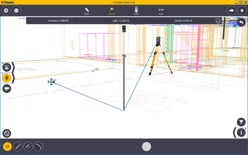
- Tap the arrow next to the Bullseye icon.
- Tap the Prism icon.
- The 3D Perspective Model View is displayed, as viewed within the model showing the position of the prism on pole or laser point if in Laser mode, the instrument location and relationship to the point being laid out.
- Directions are displayed, view & directions update as you move to the point selected.
TIP – Use of Feature Codes sets such as AB for Anchor Bolts, TR for Tree, TBC for Top Back of Curb, can help the field and office team understand collected and lay out items faster and easier. Feature Codes can also help save time in the office by automatically creating drawings or 3D model information in certain software.
NOTE – Make sure to check the backsight or stake control points periodically to ensure the instrument has not shifted locations due to settlement, thermal changes, or interference.
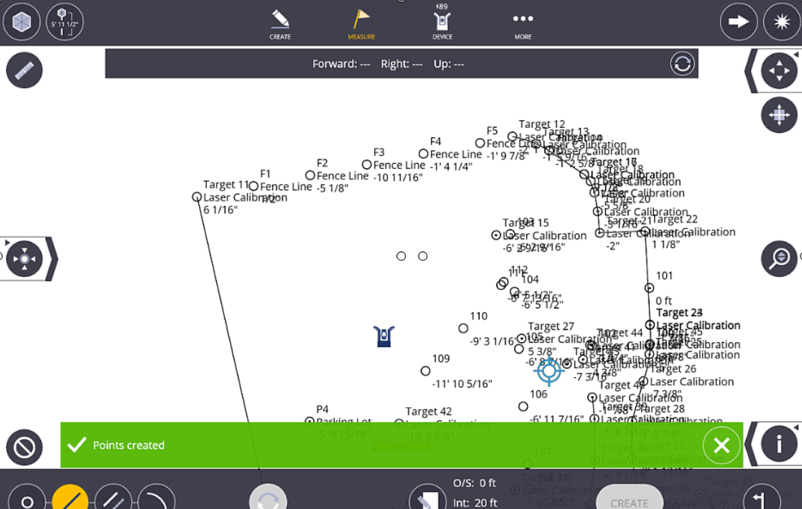
Create Points - Lay Out Line
- Tap Measure and then tap Lay Out.
- Select two points that define the line.
- Tap the Input Form icon.
- Input Offset, Interval, Start Distance, Name, Description and Layer.
- Tap Create to add points.